S C 25kV Micr AT Source Transfer Control

Product Information
Specifications
- Product Name: S&C Source-Transfer PME Pad-Mounted Gear Outdoor Distribution
- Voltage Options: 14.4 kV and 25 kV
Product Usage Instructions
Safety Precautions
It is crucial to adhere to the following safety precautions:
- Only qualified persons should install, operate, and maintain the equipment.
- Read and retain the instruction sheet for reference.
- Become familiar with safety information provided in the manual.
Overview
The product is designed for specific applications within the provided voltage ratings. Refer to the Specification Bulletin 665-31 for detailed ratings.
Installation
- Ensure only qualified persons handle the installation.
- Thoroughly read and understand the instruction sheet before proceeding.
- Store the instruction sheet in the low-voltage connection enclosure for future reference.
Dielectric Testing
Refer to section 21 of the manual for instructions on conducting dielectric testing.
FAQ
Safety Information
Understanding Safety-Alert Messages:
- Familiarize yourself with the safety-alert messages in the manual and on product labels.
- Pay attention to signal words indicating different levels of importance.
Warranty
Warranty Qualifications:
The standard warranty does not cover non-S&C manufactured components such as remote terminal units and communication devices.
Introduction
Qualified Persons
- WARNING
Only qualified persons knowledgeable in the installation, operation, and maintenance of overhead and underground electric distribution equipment, along with all associated hazards, may install, operate, and maintain the equipment covered by this publication. A qualified person is someone trained and competent in:- The skills and techniques necessary to distinguish exposed live parts from nonlive parts of electrical equipment
- The skills and techniques necessary to determine the proper approach distances corresponding to the voltages to which the qualified person will be exposed
- The proper use of special precautionary techniques, personal protective equipment, insulated and shielding materials, and insulated tools for working on or near exposed energized parts of electrical equipment These instructions are intended only for such qualified persons. They are not intended to be a substitute for adequate training and experience in safety procedures for this type of equipment.
Read this Instruction Sheet
- NOTICE
Read this instruction sheet thoroughly and carefully before installing or operating source-transfer PME Pad-Mounted Gear. Become familiar with the Safety Information on pages 4 through 5 and Safety Precautions on pages 6 through 7.
The latest version of this publication is available online in PDF format at sandc.com/en/contact-us/product-literature/.
Retain this Instruction Sheet
This instruction sheet is a permanent part of the source-transfer PME Pad-Mounted Gear. These instructions should be stored in the low-voltage connection enclosure, using the instruction manual holder.
Proper Application
- WARNING
The equipment in this publication is only intended for a specific application. The application must be within the ratings furnished for the equipment. Ratings for source-transfer PME Pad-Mounted Gear are listed in the ratings table in Specification Bulletin 665-31. Ratings for this gear are listed on the ratings label on the interior of the doors (right-hand door only for double-door models.)
Warranty
The warranty and/or obligations described in S&C’s Price Sheet 150, “Standard Condi-tions of Sale—Immediate Purchasers in the United States,” (or Price Sheet 153, “Standard Conditions of Sale—Immediate Purchasers Outside the United States”), plus any special warranty provisions, as set forth in the applicable product-line specification bulletin, are exclusive. The remedies provided in the former for breach of these warranties shall constitute the immediate purchaser’s or end user’s exclusive remedy and a fulfillment of the seller’s entire liability. In no event shall the seller’s liability to the immediate purchaser or end user exceed the price of the specific product that gives rise to the immediate purchaser’s or end user’s claim. All other warranties, whether express or implied or arising by operation of law, course of dealing, usage of trade or otherwise, are excluded. The only warranties are those stated in Price Sheet 150 (or Price Sheet 153), and THERE ARE NO EXPRESS OR IMPLIED WARRANTIES OF MERCHANTABILITY OR FITNESS FOR A PARTICULAR PURPOSE. ANY EXPRESS WARRANTY OR OTHER OBLIGATION PROVIDED IN PRICE SHEET 150 (OR PRICE SHEET 153) IS GRANTED ONLY TO THE IMMEDIATE PURCHASER AND END USER, AS DEFINED THEREIN. OTHER THAN AN END USER, NO REMOTE PURCHASER MAY RELY ON ANY AFFIRMATION OF FACT OR PROMISE THAT RELATES TO THE GOODS DESCRIBED HEREIN, ANY DESCRIPTION THAT RELATES TO THE GOODS, OR ANY REMEDIAL PROMISE INCLUDED IN PRICE SHEET 150 (OR PRICE SHEET 153).
Warranty Qualifications
The standard warranty contained in the seller’s standard conditions of sale (as set forth in Price Sheet 150) does not apply to source-transfer PME Pad-Mounted Gear where fuse units, fuse-unit end fittings, holders, refill units, or switch blades of other than S&C manufacture are used in conjunction with S&C SME Mountings. Nor does it apply to S&C source-transfer PME Pad-Mounted Gear where other than Fault Fiter® Electronic Power Fuses, S&C Switch Blades, or the current-limiting fuses listed in Table 2 of S&C Information Bulletin 660-50 are used in conjunction with Fault Fiter Electronic Power Fuse mountings and S&C Holders designed therefore, or when current-limiting fuses are applied other than as set forth under the “Recommended Voltage Ratings” section of S&C Specification Bulletin 660-50. The seller’s standard warranty does not apply to major components not of S&C manufacture, such as remote terminal units and communication devices, including hardware, software, resolution of protocol-related matters, and notification of upgrades or fixes for those devices.
Safety Information
Understanding Safety-Alert Messages
Several types of safety-alert messages may appear throughout this instruction sheet and on labels and tags attached to the product. Become familiar with these types of messages and the importance of these various signal words:
DANGER
“DANGER” identifies the most serious and immediate hazards that will likely result in serious personal injury or death if instructions, including recommended precautions, are not followed.
WARNING
“WARNING” identifies hazards or unsafe practices that can result in serious personal injury or death if instructions, including recommended precautions, are not followed.
CAUTION
“CAUTION” identifies hazards or unsafe practices that can result in minor personal injury if instructions, including recommended precautions, are not followed.
NOTICE
“NOTICE” identifies important procedures or requirements that can result in product or property damage if instructions are not followed.
Following Safety Instructions
If any portion of this instruction sheet is unclear and assistance is needed, contact the nearest S&C Sales Office or S&C Authorized Distributor. Their telephone numbers are listed on S&C’s website sandc.com, or call the S&C Global Support and Monitoring Center at 1-888-762-1100.
Replacement Instructions and Labels
If additional copies of this instruction sheet are required, contact the nearest S&C Sales Office, S&C Authorized Distributor, S&C Headquarters, or S&C Electric Canada Ltd. It is important that any missing, damaged, or faded labels on the equipment be replaced immediately. Replacement labels are available by contacting the nearest S&C Sales Office, S&C Authorized Distributor, S&C Headquarters, or S&C Electric Canada Ltd.
Location of Safety Labels


Reorder Information for Safety Labels

Safety Precautions
DANGER Pad-mounted gear contains high voltage. Failure to observe the precautions below will result in serious personal injury or death. Some of these precautions may differ from company operating procedures and rules. Where a discrepancy exists, users should follow their company’s operating procedures and rules.
- QUALIFIED PERSONS. Access to pad-mounted gear must be restricted only to qualified persons. See the “Qualified Persons” section on page 2.
- SAFETY PROCEDURES. Always follow safe operating procedures and rules.
- PERSONAL PROTECTIVE EQUIPMENT. Always use suitable protective equipment, such as rubber gloves, rubber mats, hard hats, safety glasses, and flash clothing in accordance with safe operating procedures and rules.
- SAFETY LABELS. Do not remove or obscure any of the “CAUTION,” “WARNING,” “DANGER,” and “NOTICE” labels.
- KEY INTERLOCKS.
- If optional key interlocks were furnished, they must be in place.
- Check the operating sequence of key interlocks to verify proper sequencing.
- After the pad-mounted gear is installed, either: (1) destroy the extra set of keys or (2) make them accessible only to qualified persons. This will maintain the integrity of the key-interlock scheme.
- Key interlocks are not security locks and are not substitutes for padlocks.
- HIGH-VOLTAGE ISOLATION. Switch operators and controls are isolated from high voltage in grounded metal-enclosed compartments. Access to these components is controlled by pad-lockable covers, which incorporate a nonremovable manual handle. Other low-voltage components, such as meters, selector switches, toggle switches, etc., are similarly isolated.
- OPENING DOORS. Do not force doors open. Forcing a door open can damage the latching mechanism. If optional key interlocks are provided, correctly position the interlocks so the doors can be opened.
- CLOSING AND LOCKING DOORS.
- Doors must be securely closed and latched, with padlocks in place at all times unless work is being performed inside the enclosure.
- Mini-Rupter® Switches have switch-operating shaft access covers located on the sides of the pad-mounted gear enclosure. They must be closed and padlocked at all times unless the switches are being operated.
- Do not close a door on a TransFuser™ Mounting in the Open position with a fuse in the mounting. The door will strike the fuse pulling, which will interfere with door closing. The door may be closed if the fuse is removed from the mounting.
- ENERGIZED TERMINALS. Always assume both sets of power terminals on any Mini-Rupter Switch or fuse are energized unless proved otherwise by test, by visual evidence of open-circuit conditions on both sets of terminals, or by observing that both sets of terminals are grounded.
- BACKFEED. Mini-rupter switches and fuses may be energized by backfeed.
- DE-ENERGIZING, TESTING, AND GROUNDING. Before touching any device that is to be inspected, replaced, serviced, or repaired in the high-voltage compartments, always disconnect Mini-Rupter Switches and fuses from all power sources (including backfeed), test for voltage, and properly ground.
- TESTING. Test for voltage on both sets of power terminals of any Mini-Rupter Switch or fuse using proper high-voltage test equipment before touching any device that is to be inspected, replaced, serviced, or repaired in the high-voltage compartments.
- GROUNDING.
- Make sure the pad-mounted gear enclosure is properly grounded to the station or facility ground.
- After the gear has been completely disconnected from all sources of power and tested for voltage, install suitable grounding cables in all compartments before touching any device that is to be inspected, replaced, serviced, or repaired in the high-voltage compartments.
- SWITCH POSITION.
- Always confirm the Open/Close position of Mini-Rupter Switches by visually observing the position of the switchblades.
- Switches may be energized by backfeed.
- Switches may be energized in any position.
- MAINTAINING PROPER CLEARANCE. Always maintain proper clearance from energized components.
- FUSE STORAGE.
- Always store fuses in a clean, dry location.
- Do not store end-fittings, holders, interrupting modules, or fuses in termination compartments unless the unit is equipped with the optional Fuse Storage feature.
Overview
The following instructions cover installation of S&C Source-Transfer PME Pad-Mounted Gear equipped with the Micro-AT Source-Transfer Control. This gear is a totally self-contained switching and protection package that provides fault protection and fully automatic two-way source transfer for critical loads requiring a high degree of service continuity. Source-transfer PME models include the S&C Micro-AT Source-Transfer Control for programmed control of all switching functions associated with automatic source transfer.
Refer to S&C Instruction Sheet 665-610 for instructions regarding operation of Source-Transfer PME Pad-Mounted Gear. For instructions regarding field programming and operation of the Micro-AT control, refer to S&C Instruction Sheet 515-500. These instruction sheets, along with a catalog dimensional drawing showing cable-locating and anchorbolt dimensions, are included in the “Installation and Operation Information Kit” provided with the gear. Wiring diagrams for the gear and associated options are also provided in the kit. All personnel involved with the installation and operation of the equipment should be thoroughly familiar with the contents of the information kit. The catalog number stamped on the nameplates affixed to the outside of the doors of the pad-mounted gear is suffixed with letter-number combinations. These suffixes indicate the inclusion of optional features. Refer to Table 4 of S&C Specification Bulletin 665-31 for a complete listing of the available options for the gear.
Shipping and Handling
Storage
NOTICE S&C Source-Transfer PME Pad-Mounted Gear should preferably be installed and energized immediately. When the gear is energized, voltage sensor secondary-burden resistors generate sufficient heat to help prevent condensation in the low-voltage control compartment. If the gear cannot be installed immediately, store it in a clean, warm, dry room.
Packing
S&C Source-Transfer PME Pad-Mounted Gear is fastened to a wood skid for shipment. Any components specified, such as fuses, refill units, fuse holders, end-fittings, etc., are packed separately and, insofar as practicable, are shipped within the enclosure. At the first opportunity, remove all packing materials (cardboard, paper, foam padding, etc.) from the outside of the gear. This will prevent the finish from being damaged by rainwater absorbed by the packing materials and will also prevent wind-induced abrasion from loose cardboard.
Inspection
Examine the shipment for external evidence of damage as soon after receipt as possible, preferably before removal from the carrier’s conveyance. Check the bill of lading to make sure all listed shipping skids, crates, and containers l are present.
- If there is visible loss and/or damage:
- Notify the delivering carrier immediately.
- Ask for a carrier inspection.
- Note the condition of shipment on all copies of the delivery receipt.
- File a claim with the carrier.
- If concealed damage is discovered:
- Notify the delivering carrier within 15 days of receipt of shipment.
- Ask for a carrier inspection.
- File a claim with the carrier.
Also, notify S&C Electric Company in all instances of loss and/or damage.
Handling
WARNING When handling the gear with an overhead hoist, observe standard lifting practices and the general instructions below. Failure to follow these precautions can result in serious personal injury or equipment damage
Complete the following steps when lifting the gear:
- Step 1. Make sure the lifting tabs are securely bolted to the enclosure before lifting the gear.
- Step 2. Use 6‑foot (183 cm) or longer hoist slings of equal length to prevent overstressing the enclosure during lifting. (4‑foot [122‑cm] hoist slings are acceptable for two-compartment pad-mounted gear models: PME-4 and -5.)
WARNING Because the sides of the gear where the low-voltage control compartment is located are heavier than the other sides, the gear may tilt when lifting. Therefore, care must be taken when lifting the gear to avoid injury and equipment damage. - Step 3. Arrange the hoist slings to distribute the lifting forces equally between the lifting tabs. See Figure 1.

- Step 4. Avoid sudden starts and stops.
Installation
Access to Interior
NOTICE Do not apply any undue force when attempting to open the doors. The use of undue force may damage the latching mechanism.
Access to the interior of S&C Pad-Mounted Gear is controlled by the S&C Penta-Latch® Mechanism, which must be opened with a pentahead socket wrench or tool except when hexhead actuators are specified. The latching mechanism is coordinated with the provisions for padlocking so the mechanism can be unlatched only after the padlock has been removed, and the padlock can be installed only after the door has been securely closed and completely latched.
Opening the Front Doors
Complete the following steps to open the doors:
- Step 1. Use a pentahead socket wrench or tool (a hexhead socket wrench or tool when catalog number suffix “-B1” or “-B2” is specified) to unlatch the Penta-Latch Mechanism by rotating the actuator counterclockwise approximately 60º against spring resistance until a distinct “click” is heard and the actuator reaches its stop. Refer to Figure 2. This single motion unlatches the mechanism and recharges the latching spring for the subsequent closing operation.

- Step 2. Pull the door open and secure it with the door holder.
NOTICE If optional key interlocks are furnished, correctly position the interlocks so the doors can be opened. - Step 3. For double-door models of pad-mounted gear: The left-hand door is secured closed by a rotating latch and is overlapped by the right-hand door which is equipped with the Penta-Latch Mechanism. The left-hand door can be opened after opening the right-hand door and disengaging the rotating latch. To disengage the latch, rotate it upward. See Figure 6 on page 13.
The left-hand door to the low-voltage control compartment is secured closed by two captive screws and is overlapped by the right-hand door, which is equipped with the Penta-Latch Mechanism. This door can be opened after opening the door equipped with the Penta-Latch Mechanism and loosening the screws securing it in place.
Opening the Roof Section
The roof section over each cable compartment is hinged to allow easy cable pulling during installation.
To open the roof section over a cable compartment, complete the following steps:
- Step 1. Remove the 3/8–16‑inch standard ESNA nuts, 3/8‑inch standard washers, and the 3/8‑inch large washers that attach the roof sections to the PME Pad-Mounted Gear enclosure. Each roof section will have 3 ESNA nuts, 3 standard washers, and 3 large washers (2 of each for two compartment models: PME-4 and -5). See Figure 3 for location of hardware.

- Step 2. After removing the roof hardware, the springloaded roof section will pop up slightly. See Figure 4. A mechanical interlock, furnished in each door containing a Penta-Latch® Mechanism, prevents the door from closing and latching when the roof section is not secured to the enclosure.
- Step 3. Lift up the roof section and latch it at both ends using the supplied retainers. See Figure 5.

Closing the Roof Section
To close the roof section, complete the following steps:
- Step 1. Remove the retainers from the roof section and place them in the horizontal position.
- Step 2. Lower the roof section.
- Step 3. While applying force to the roof section, secure the roof to the enclosure using the 3/8‑inch large flat washers, 3/8‑inch standard washers, and 3/8–16‑inch ESNA nuts. It is recommended to tighten the center hardware first. Additional roof hardware is shipped with the PME Pad-Mounted Gear.
Note: A mechanical interlock, furnished in each door containing a Penta-Latch® Mechanism prevents the door from closing and latching when the roof section is not secured to the enclosure.
Closing the Front Doors
- Step 1. Close the left-hand door, where applicable, and secure it with the latch by rotating the latch downward over the stop on the outer edge of the door. See Figure 6.
 The right-hand door of double-door models of pad-mounted gear is equipped with the Penta-Latch Mechanism which latches automatically when the door is closed. To close a door equipped with the Penta-Latch Mechanism: Place one hand at the midpoint of the door-front near the edge and firmly push the door closed. See Figure 2 on page 11. When the latch points are positively engaged, the spring mechanism will trip to latch the door.
 - Step 2. Check the roof to make sure all sections are properly secured. If the roof section is not latched to the pad-mounted gear, a mechanical interlock in the right-hand door will prevent the door from properly latching.
- Step 3. Pull outward on the cover of the Penta-Latch Mechanism to verify the door has latched securely. If it has not, use a pentahead (or hexhead, when applicable) socket wrench or tool to rotate the actuator counterclockwise until a distinct “click” is heard and the actuator reaches its stop. If the actuator will not rotate counterclockwise, the mechanism was already charged for closing but was not closed properly. Close the door again, making sure that all latch points engage completely and simultaneously.
- Step 4. Insert a padlock into the hasp when the door is securely latched.
Placing the Gear
Complete the following steps when placing the gear:
- Step 1. At the installation site, remove all separately packaged components that were shipped within the pad-mounted gear enclosure and set them aside in a protected area.
- Step 2. Unbolt the enclosure from its skid and lift the unit onto the mounting pad, observing the precautions given in the “Shipping and Handling” section on page 10.
- Step 3. Open the doors to the interior of the gear and secure them with the door holders.
- Step 4. Refer to the catalog dimensional drawing furnished and verify the enclosure compartments are positioned correctly and the unit is properly aligned with respect to the anchor bolts (or flush anchors).
Note: If excess lengths of direct-buried cable are in place and it is desired to feed them into the termination compartments as the unit is being lowered, special attention must be paid to cable position in the termination compartments for fuses.
First, the doors must be opened (with door holders in place) to allow any excess cable to be fed over the door stiles. Then, as the enclosure is being lowered into place, the cables for connection to the fuse terminals must be fed between the horizontal cable guides as shown in Figure 7 and on the cable-training tag affixed to the enclosure.
Note: Cables for connection to the fuse terminals must be fed between the horizontal cable guides so they will not interfere with TransFuser™ Mounting operation. Special cable training is not required in the termination compartments for switches. - Step 5. Level the pad-mounted gear enclosure using metal shims as required between the mounting pad and the enclosure. Shim the enclosure of four-compartment units until the tops of the compartment doors are even. For two-compartment units: Shim the enclosure until the top of each door is parallel with the top of the gear.
- Step 6. Secure the enclosure to the pad using the anchor brackets provided (see anchor-bolt detail on the catalog dimensional drawing). Make sure all compartment doors open and latch closed without binding. Binding indicates enclosure distortion which must be corrected by additional shimming.
Note: If the pad-mounted gear is installed on a pad with cables in conduit, the roof sections over the cable compartments can be opened to allow the cables to be pulled up through the roof opening rather than the door opening.
Cable Terminations
WARNING Before energizing the gear, replace the shipping caps on all bushings and bushing wells with elbows or insulated protective covers or plugs. Failure to replace the shipping caps can result in a flashover and serious personal injury or death.
Switch terminals are equipped with 600‑ampere-rated bushings, and fuse terminals are equipped with 200‑ampere-rated bushing wells. Bushing and bushing- well interfaces conform to ANSI/IEEE Standard 386 to accept all standard separable insulated connectors—“ elbows”—and inserts. Appropriate elbows● and inserts must be supplied and installed by the user.
Complete the following steps to terminate cables:
- Step 1. Before installing elbows and inserts, remove the shipping covers from bushings and bushing wells.
- Step 2. Ground each insert by connecting a short ground wire from the insert to the ground tab directly above the bushing well. See Figure 7 on page 14.
WARNING When grounding inserts, minimize the length of the ground wire. Use of a longer ground wire can result in a flashover to energized parts inside the component compartment and serious personal injury or death when the TransFuser Mounting is rotated to the closed position. - Step 3. Verify cables in termination compartments for fuses are correctly positioned between the cable guides. Then, terminate the cables with the elbows, following the elbow manufacturer’s instructions.
NOTICE Do not allow solvents used to clean cables prior to termination to contact the viewing windows. The solvent can permanently etch the polycarbonate material.
The 600‑ampere bushings supplied in S&C Source-Transfer PME Pad-Mounted Gear are equipped with a stud as standard. Bushings are available without studs to accommodate 600‑ampere elbows that do not require a stud. See Figure 8.
- NOTICE
Do not install vertical-type feedthrus on the parking stands of fuse-termination compartments of gear equipped with SME-20 Power Fuse Mountings or Fault Fiter Electronic Power Fuse Mountings. The eyebolt of the feedthru can damage the blown-fuse viewing window - Step 4. Connect the cable concentric-neutral ground wires to the ground bails and rods provided, making sure that cables have sufficient mobility to allow the elbows to be moved from bushings to parking stands.
- Step 5. Connect the ground pads inside the pad-mounted gear enclosure to the system ground facility in accordance with the user’s standard grounding practice. Use the equivalent of 4/0 copper cable (or cable sized in accordance with the user’s standard practice) in either a single or multiple connection to realize the maximum momentary rating of the gear. For a multiple connection, cables smaller than 1/0 copper or equivalent should not be used.
NOTICE Concentric-neutral ground wires must be positioned so that they will not interfere with TransFuser Mounting operation when the elbows are on the parking stands.
CAUTION Low-voltage wiring routed inside the pad-mounted gear enclosure must be a minimum of 6 inches (152 mm) at 14.4 kV and 71/2 inches (191 mm) at 25 kV away from components that will be energized at high voltage. In addition, do not place wiring where it might fall onto a component that will be energized at high voltage, such as the bus, or where it will be in the way of the moving parts. Failure to maintain proper clearances can result in a flashover, injury, and equipment damage.
NOTICE Openings made into the low-voltage control compartment must be sealed with a suitable compound to prevent the entry of moisture or rodents. Failure to properly seal the openings can result in damage to the electronic components.
NOTICE Do not install the current sensors on unshielded cables or on cables where the insulation is exposed but ungrounded (for example, where dielectric tape or heat shrink tubing is used). These current sensors are intended for application at ground potential and can be damaged by the voltage gradient between the cable insulation and ground.
S&C Current Sensors
Six S&C Current Sensors—packed separately—are provided for units furnished with the optional Overcurrent Lockout feature. The leads from the current sensors in each switch compartment are to be connected to a terminal block located in the associated terminal- block compartment, behind the bolted panel labeled “Terminal Blocks.” See Figure 9.
The bottom plate in each terminal-block compartment is removable to facilitate makeup of an entrance hole for the lead wires. If conduit is not used, protect the lead wires from abrasion against the knockout opening with a rubber grommet or by taping. Then, apply a suitable compound to fill the space between the lead wires and the opening to prevent entry of moisture or rodents.
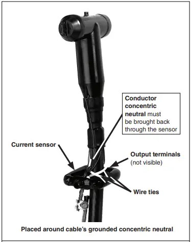
Refer to the applicable wiring diagram and make the appropriate connections from the current sensors (with polarity marks on top) to the terminal blocks. Then, attach each current sensor to its associated high-voltage cable as follows:
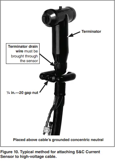
- Step 1. Remove the 1/4 in.—20 gap nut on the current sensor. With polarity marks on top, open the current sensor and place it around the appropriate high-voltage cable. Now replace and securely tighten the gap nut.
- Step 2. Secure the current sensor to the high-voltage cable at a point below the cable terminator or stress cone using the plastic wire ties furnished. See Figure 10. The current sensor may be placed against the cable’s grounded concentric neutral in which case the concentric neutral must be brought back through the sensor, or it may be placed against the cable’s semiconducting jacket, in which case the terminator’s drain wire must be brought through the sensor.
Note: The terminal blocks furnished with the optional auxiliary switches, optional remote-indication feature, or optional Supervisory Control feature are also located in the terminal-block compartments. Refer to the applicable wiring diagram and make the connections as required.
Step 3. Connect the cable concentric-neutral ground wires and ground pads inside the pad-mounted gear enclosure to the system ground facility by the user’s standard grounding practice.
Use the equivalent of 4/0 copper cable (or cable sized by the user’s standard practice) in either a single or multiple connection to realize the maximum momentary rating of the gear. For a multiple connection, cables smaller than 1/0 copper or equivalent should not be used.
Fault Indicators
Optional mounting provisions for fault indicators are available. Fault indicators are to be furnished by the user and installed by the manufacturer’s instructions. If mounting provisions are specified, mount the fault indicators on the mounting brackets and attach the associated sensors to the cables below the cable terminators.
Completing the Installation
Complete the following steps to complete the installation:
- Step 1. Check functional operation of key interlocks, if furnished.
WARNING An extra set of keys is provided with pad-mounted gear that has optional key interlocks. These keys are for use only during installation. After installation, either: (1) destroy the extra set of keys or (2) make them accessible only to authorized persons. This will maintain the integrity of the key-interlock scheme. Failure to maintain the integrity of the key interlock scheme may lead to equipment damage, personal injury, or death.
NOTICE Key interlocks are not security locks and are not a substitute for padlocks.
NOTICE Do not apply any undue force when attempting to open the doors. The use of undue force may damage the latching mechanism. Also, if optional key interlocks are furnished, correctly position the interlocks so the doors can be opened. - Step 2. Make sure doors open and close without binding and that shimming of the pad-mounted gear enclosure is adequate.
- Step 3. Check for space between the enclosure gasket and the foundation. A resilient closed-cell gasket on the bottom flange of the enclosure protects the finish from being scratched during installation and isolates it from the alkalinity of a concrete foundation. This gasket also helps to seal the enclosure to the foundation to guard against entry of rodents, insects, or weeds, and to discourage tampering. If the gasket cannot compensate for an uneven foundation, grout the bottom of the enclosure as necessary. Any grout applied should be recessed enough to permit caulking.
- Step 4. Caulk around the bottom of the enclosure with a weatherproof compound applied with a standard caulking gun. A room-temperature vulcanizing (RTV) silicon-rubber compound is recommended.
- Step 5. Apply a suitable compound to fill the spaces between the cable and the conduit, and cap all empty conduits to prevent the entry of moisture or rodents.
- Step 6. Remove the lifting tabs and replace the bolts to plug the blind-tapped holes.
- Step 7. Check the interior of the pad-mounted gear. Remove all foreign materials and tools that may have been mislaid, and sweep the interior clear of debris.
- Step 8. Store spare SMU-20® Fuse Units, SM-4® Refill Units, or Fault Fiter fuse interrupting modules (as applicable) in the fuse-storage racks inside the fuse-compartment doors.
- Step 9. Wipe down the exterior of the enclosure with a clean, damp cloth. To preserve the integrity of the surface, refinish any scratches or abrasions with S&C touch-up finish and red-oxide primer which are available in aerosol spray cans. See S&C Specification Bulletin 665-31 for catalog number information used for ordering. No other finish or primer is approved. The area to be touched up should be cleaned to remove all oil and grease. Sand the area, removing any traces of rust that may be present, and make sure that all edges are feathered before applying primer.
Note: Labels indicating the area around the pad-mounted gear that must be kept clear so that work on the gear can be done safely are provided in the “Installation and Operation Information Kit.” These labels (or equivalent labels) should be affixed to the exterior of the gear. Refer to Figure 2 on page 11. Upon completion of these installation instructions, refer to S&C Instruction Sheet 665-610 for operating instructions.
Dielectric Testing
When high-voltage dielectric tests are to be performed on S&C Source-Transfer PME Pad-Mounted Gear, special precautions should be taken to prevent damage to the voltage sensor(s) and voltage limiters. Refer to S&C Instruction Sheet 591-500.
March 18, 2024
© S&C Electric Company 1998–2024, all rights reserved
Documents / Resources
 |
S C 25kV Micr AT Source Transfer Control [pdf] Instruction Manual 25kV Micr AT Source Transfer Control, 25kV, Micr AT Source Transfer Control, Source Transfer Control, Transfer Control |