
![]() User Guide: Multilog IS
User Guide: Multilog IS
(part 1 of 2) Installation and Setup. 
MAN-156-0001 Multilog IS Certified Logger Built with a Variety of Sensors
![]() Warning: This manual contains important safety and operating information.
Warning: This manual contains important safety and operating information.
Please read, understand, and follow the instructions in the manual and also any safety / approvals or Intrinsic Safety (ATEX or IECEx or UKEx)
Safety Supplement documents shipped with the device.
INTRODUCTION
1.1 DOCUMENTATION AND SUPPORT OF PRODUCT
Thank you for choosing a HWM device. We trust it will provide you with many years of service.
The “Multilog IS” is a multi-purpose data logger device that can be built and configured to suit specific applications; several models are available. Please contact your sales representative for help with selection of an appropriate model for your application.
This user-guide covers the following model families:
Model Number(s) Description
MLIS*/*/*/IS/* Multilog IS logger. (Intrinsically safe models).
The user-guide should be read in conjunction with:
MANEX-156-0001 Multilog IS User Manual (Part 2 of 2) – Safety Supplement.
MAN-156-0002 Multilog IS Safety Warnings and Approvals Information.
MAN-2000-0001 IDT (mobile app version) user-guide.
This user-guide provides details of the logger operation, how to install the product. You should also read the relevant parts of the IDT app user-guide for guidance on how to confirm settings or modify the set-up your logger. Also refer to any user-guides or datasheets for sensors that are applicable for your particular installation.
To view your data a viewing tool is required; refer to any user-guide or training materials relevant to the tool you will be using (see also section 2.4).
Note: The system periodically has new features and changes released, thus you may observe slight changes from the diagrams and features shown in this manual.
In addition, the screen shots and menu descriptions used throughout this manual refer to the specific functionality that was installed within the logger samples used. This can vary from device to device, therefore always refer to the menus and screens of any setup tool to determine which features are available on your device.
HWM provides support of the logger devices by means of our customer support webpages: https://www.hwmglobal.com/help-and-downloads/
Should you have any questions that are not covered by this manual or the system’s online help, please contact the HWM Technical Support team on +44 (0) 1633 489479, or email cservice@hwm-water.com
Acknowledgements:
![]() The Bluetooth ® word mark and logos are registered trademarks owned by Bluetooth SIG, Inc. and any use of such marks by HWM-water Ltd is under license. Other trademarks and trade names are those of their respective owners.
The Bluetooth ® word mark and logos are registered trademarks owned by Bluetooth SIG, Inc. and any use of such marks by HWM-water Ltd is under license. Other trademarks and trade names are those of their respective owners.
1.2 SAFETY CONSIDERATIONS
The “Multilog IS” is an intrinsically safe logging device.
Certification includes the following schemes (dependant on model):
- ATEX
- UKEx
- IECEx
Note: Where this manual uses the terms “Intrinsically Safe” or “ATEX” throughout its content, this must be understood to mean whatever intrinsic safety standards (ATEX, UKEx, IECEx) are relevant or applicable to the country of installation.
The installer is responsible for ensuring the logger and any peripheral equipment are certified for use and also compatible for interconnection.
Safety Note:
Before continuing, carefully read and follow the information in the “Safety Warnings and Approvals Information” document supplied with the product.
This provides general safety information.
The installer or maintainer must also refer to any other safety supplement documents, supplied with intrinsically safe versions of the product. This will provide additional ATEX-related safety information, including port parameters.
(“ATEX” refers to use of the product within a potentially explosive atmosphere).
Retain all documents for future reference.
Before using this product:
- Make a risk assessment of the installation site and expected work activity.
- Installations in a hazardous environment (e.g., ATEX) should be carried out by appropriate technicians with suitable training for that environment.
- Ensure any tools necessary for installation are suitable for use within the hazardous environment.
- Ensure suitable protective clothing is worn and working practices are followed during installation and any maintenance.
- Check with the site owner or supervisor for any additional safety requirements before commencing work.
- Ensure any communications device being used to assist in the install or setup of the logger is also suitable for use in any hazardous environment in which you are working.
Within an ATEX environment, only use an Intrinsically Safe model of the logger: - Confirm the model number is for an intrinsically safe unit.
- Confirm that the logger label has suitable ATEX markings.
Before connecting the logger to sensors or other apparatus: - Check the sensor or apparatus is approved and certified for use within the intended installation environment.
- Confirm the equipment has suitable ATEX markings and is being operated within its ATEX limits.
- Check the port parameters of the relevant logger interface and the equipment to be attached. Confirm they are suitable for interconnection.
- Check the equipment has a suitable cable and connector attached for interconnecting to the logger interface. A water-tight connection is required.
For an ATEX environment, any materials used, and workmanship must meet the required ATEX standards.
Note: The logger can also be used in non-ATEX applications.
1.3 OPERATING TEMPERATURE
Refer to the logger Datasheet or your sales representative for guidance on the storage and operating temperature range of the device. Ensure the unit is within the operating temperature range prior to installation.
1.4 CROSS-REFERENCE: CONNECTOR – CIRCUIT ENTITY – IDT DESCRIPTION
The logger interface descriptions can sometimes vary between the labelling of the connection (see logger labels), the entity parameters (see the Safety Supplement document), and the description of the interface within IDT (see IDT app and its userguide). The following cross-reference table is provided for your information:
| Logger Connector Label | Circuit Entity |
IDT description |
| ANTENNA | ANTENNA | (none) |
| EXT POWER | EXT POWER | (none) |
| PASSIVE 4-20mA | PASSIVE 4-20mA | 4-20mA[n] |
| ACTIVE 4-20mA | ACTIVE 4-20mA | 4-20mA[n] |
| DIGITAL SENSOR | DIGITAL SENSOR | SpillSens[n] (Sensor dependent) |
| EXTERNAL PRESSURE | EXTERNAL PRESSURE | Pressure[n] |
| FLOW SINGLE BIDIRECTIONAL | FLOW | Pulse [n] |
| FLOW DUAL UNIDIRECTIONAL | FLOW | Pulse [n] |
| STATUS OUTPUT SINGLE | PULSE REPLICATION OUTPUT | output[n] or [n] |
| STATUS OUTPUT DUAL | PULSE REPLICATION OUTPUT | output[n] or [n] |
| RS485 (12V) | RS485 (12V) | Serial [n], [n] RS485 (12V) |
| RS485 (9V5) | RS485 (9.5V) | Serial [n], [n] RS485 (9.5V) |
| RS485 (7V5) | RS485 (7.5V) | Serial [n], [n] RS485 (7.5V) |
| SDI-12 (12V) | SDI-12 (12V) | Serial [n], [n] SDI-12 (12V) |
| SDI-12 (9V5) | SDI-12 (9.5V) | Serial [n], [n] SDI-12 (9.5V) |
| SDI-12 (7V5) | SDI-12 (7.5V) | Serial [n], [n] SDI-12 (7.5V) |
| RTD (TEMP) | RTD (TEMP) | Pressure[n] |
| RADARSENS | SONICSENS | RadarSens Measure |
| SONICSENS 3 (ULTRASONIC) | SONICSENS | SonicSens Measure |
| 0-1V SINGLE | 0-1V | 0-1V[n] |
| 0-1V DUAL | 0-1V | 0-1V[n] |
| 0-10V SINGLE | 0-10V | 0-10V[n] |
(“[n]” is an enumerator, required to make interfaces of the same type distinct from each other).
OVERVIEW AND PREPARATION FOR USE
2.1 LOGGER – PHYSICAL FEATURES & CONNECTOR IDENTIFICATION
The Multilog IS logger family is flexible in design and can be built to suit a variety of uses.
An example is shown opposite. Your logger may be different to the one illustrated; several models exist within the Multilog IS family.
The logger has a waterproof construction and has waterproof connectors for attaching sensors and antenna. The connectors can exit the unit via either the top or bottom of the case.
The logger includes 4 keyhole shaped mounting holes, (spaced 300mm x 157mm apart).
The logger may be fixed to a wall using flat-headed screws using the holes.
There are 3 additional holes passing through both sides of the case; these can be used for applications requiring anti-tamper seals to be applied.
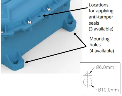
The top of the unit can be identified using the shape of the keyholes.


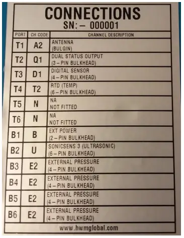
The logger contains another label, “Connections”.
The label has a table specifying the type of interface that is fitted at each of the 12 positions (T1 ~ T6, B1~ B6).
Note: The table content will vary according to the model supplied. Vacant connector locations will be listed as “NA”.
Connector locations vary according to the model-number of the logger.
 Where there are multiple interfaces of the same type, the user can usually determine how the connector is related to the numbering of the inputs within the IDT setup pages.
As a general guideline, the interface connector using the lowest numbered ports (hardware input channels, as shown in IDT) will be on the left-hand side of the logger.
This starts at B2, proceeds along to B6, then moves to T2 and proceeds along to T6. e.g. A logger model has a FLOW input fitted at location T2 and also at B4:
In the sequence B2 to B6 followed by T2 to T6 …
B4 occurs first and T2 occurs second.
Therefore, B4 will be given the lowest IDT hardware channels (Pulse 1&2) and T2 will be given the next IDT hardware channels (Pulse 3&4).
There are very rare exceptions to this rule. (e.g., see section 4.7.1). Suitable confirmation tests are given in section 6.
2.2 PREPARING A MOBILE PHONE (OR SIMILAR DEVICE) FOR USE WITH LOGGERS
The Multilog IS requires a user-interface in order to setup and test the unit. This is provided by means of an app which is to be installed onto a mobile phone (or similar device).
The mobile phone must have:
- Bluetooth Low Energy radio compatibility,
- GPS functionality,
- Internet capability.
The HWM “IDT app” is the required app.
Refer to the IDT app User Guide for details of its installation and general use during installation. Follow the directions including installing any additional apps that are required.
The installer is required to be familiar with the use of IDT and any other required apps.
The IDT app user guide covers many interface types. Refer the relevant sections during installation for guidance on how to setup the Multilog IS logger; This will be dependent on the interfaces fitted and sensors being installed.
2.3 LOGGER OPERATION
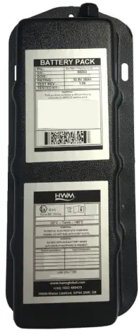
The logger is powered by a non-rechargeable Lithium battery. The software is designed to minimise battery use and thereby prolong the expected battery life. However, battery life is also affected by user-programable settings. The user is advised to set the logger to keep tasks and sample frequencies to the minimum requirements of the intended use in order to manage battery power effectively.
The unit can also operate from an (optional) additional external HWM battery unit (see opposite).
Where supplied, the external battery power is used to extend the battery life of the logger or to allow more frequent communications with the host server.
When the logger is used with certain combinations of sensors, the use of an external battery is mandatory (Refer to section 5.3, and also the advice of your HWM representative).
 The logger is normally shipped from the factory in an inactive state (referred to as “shipping mode”) to preserve the life of the battery.
When activated (see section 3.1), the logger will go into the state of “Recording” and begin repetitive logging of the various sensors fitted to the unit, according to its configuration and settings.
The logger can operate using two time periods, known as the “sample period” and the “log period”. It will sample the sensors at the sample rate to create temporary measurement samples; this is a repetitive background task. After taking several measurement samples, some statistical functions can be optionally applied to produce a datapoint that is logged (saved) at the log rate; these form the recorded (logged) measurements and are saved into an area of memory which is referred to as the “primary recording”. The log period is always a multiple of the sample period.
If the logger has the feature enabled, it can also be set to occasionally save additional data into a “secondary recording” memory area, (e.g., data sampled at a higher frequency, such as by using the “sample period” rather than the “log period”).
Note: This is not available on all supplied units and must be arranged through your sales representative before placing an order; it has implications concerning expected battery life of the unit).
In addition, the logger will have daily tasks at set times, such as uploading its un-sent data over the internet. When sending data, the logger waits to receive confirmation from the server that the data was received without error; If confirmation is not received, it will re-send the data at the next call-in time.
The logger can be programmed to monitor data for certain patterns or conditions and can send a message if it should detect a match. Commonly, this is used for setting a condition that can be an indication of an “alarm”. The message can be sent to either the server (the usual destination) or another device.
(The IDT app user-guide also provides an introduction to basic HWM logger operation; this may provide further information).
2.4 SERVER INTEGRATION – STORING AND VIEWING DATA
The Multilog IS logger includes an interface (referred to as a modem) that provides access to the internet via the cellular mobile communications network. A SIM card is used to give access of the network.
Measurement data is initially stored within the logger, until the next call-in time. The data can then be uploaded to the server using an encrypted format. Typically, the server used to receive and store the data will be an HWM DataGate server, although other servers may be used in conjunction with HWM software.
The logger data may be viewed using a viewing portal which has access to the data stored on the server. (Refer to the relevant user guide for details of how your data viewer can be used to view the logger data).
2.4.1 DataGate Server / Data viewing portals
When integrated with HWM’s DataGate server, the logger’s measurement data can be stored centrally and made available to users via a viewing portal (website). The data storage server can handle receipt and storage of data from a single unit, or from an entire fleet of loggers.

The data from your logger(s) can be viewed remotely /graphically by anyone authorised to do so, with a suitable user account (and password) using a standard web-browser.
HWM has a selection of websites that can be used to view logger data. The best choice of website depends upon the type of sensors used with the logger.
A website with a generic data viewer can show data graphically for one logger at a time, installed on one site. However, a website which can show a fleet of loggers, each having the same type of sensor, can often present data in a more meaningful way to the user, along with useful supplementary information (e.g., a map showing the logger locations). Thus, a website may allow visualisation of the current status of many sites at one time.
Refer to the IDT app user guide or sensor user-guide for details of which viewing portal is most appropriate to use. Alternatively, discuss this issue with your HWM representative.
The DataGate server can also forward any alarms received from the logger to all users that have subscribed to them; one logger alarm message can therefore be distributed to multiple DataGate users.
Use of the loggers with the DataGate system can offer security features for certain loggers (see section 2.5).
DataGate can also (by arrangement with your sales representative) be used to export logger data to other servers.
Some administrative setup of the server and of the viewing portal is normally required to facilitate receiving, storing, and presenting logger data correctly. Setup of and use of the DataGate system (or any other server) are not covered by this user guide.
Note: Some loggers have a specific requirement to be used with DataGate in order to meet their security features (if enabled). (See section 2.5).
2.5 LOGGER SECURITY: SECURE AND UNPROTECTED MODES
The Multilog IS logger has certain security feature options. Refer to the IDT app userguide for an explanation of each option.
2.6 CHANNEL CAPACITY
The channel capacity of the Multilog IS should be restricted by the user to allow you to view all available data on the chosen data-viewing tool (web portal). This is typically 8 primary data recording channels; however, this should be discussed with your HWM representative when selecting from the available the web portals.
ACTIVATING THE LOGGER AND COMMUNICATIONS LINK
3.1 LOGGER ACTIVATION PROCESS (FOR FIRST-TIME USE)
When shipped from the factory, the unit is deactivated. This mode is designed to preserve its battery life whilst being shipped or in long term storage; this is often called “shipping mode”. To use the logger, it must first be activated. The process for doing this is the same as required to activate its Bluetooth ® communications link (refer to section 3.2).
3.2 COMMUNICATIONS LINK FOR USE WITH IDT
The logger includes a Bluetooth® radio interface, used for short-range communication to a mobile phone. This enables the user to communicate with the logger using the IDT app during installation and on-site test. (No communications cable is required). The Bluetooth® radio interface is infrequently needed (it is only required when someone is attending to the logger on-site). The communications circuit is therefore normally on standby.
To temporarily activate the communications, a magnet is required.
On the side of the logger there is a label showing a magnet symbol. A magnetic field sensor is located under this label.
A strong magnet must be constantly held in front of the label for 12 seconds to activate the communications link.
(Suitable magnets can be purchased from many hardware stores).
 Communication remains open for around 120 seconds, but this period is extended if communications is in use; the communication link remains open for 600s after it was last used. The link then goes back into standby.
Note: This action is sometimes referred to as “swiping the logger”. Because of the communications is over a radio link, it is possible that IDT will pick up more than one logger (or other devices) that are in range. To communicate with the logger, it must be selected from within IDT. For instructions on how to do this, refer to the IDT app User-guide.
3.3 ACCESS CONSIDERATIONS
Whenever choosing a location to mount the logger, ensure there is sufficient space at the side of the unit to access the magnetic sensor with the magnet tool. This will allow the logger communications link to be activated without the need to remove it. Allow sufficient access space for logger connections to be fitted and removed.

INTERFACES AND SENSORS SUPPORTED
Note: Support for specific interfaces or functions vary and are dependent upon the model supplied.
4.1 AVAILABLE SENSORS
When installing the Multilog IS within an ATEX environment, all attached sensors and installation cables must meet ATEX requirements.
Multilog IS has sensors and / or interfaces available to measure many parameters, including:
- Pressure
- Temperature
- Distance to a water surface
- Water depth
- Water velocity
- Water flow rate (volume per second / total consumption)
- (Others). Contact your sales rep for more information or to discuss your requirements.
Sensors provided by HWM will include a cable with a suitable connector for the Multilog IS.
4.2 LOGGER INTERFACES
Sensors sense various physical parameters, and this information is transferred to the logger via an appropriate electrical interface. A software driver is required to interpret the electrical signals.
Multilog IS has a variety of electrical interfaces and software drivers to support some of the most widely used sensor signalling methods.
The interfaces vary in characteristic; some are analogue in nature (e.g., voltage or current); some are digital in nature (e.g., an open / closed switch); some are built around data transfer over a serial communications link (e.g., SDI-12 and RS485).
4.3 INTERFACES SUPPORTED BY MULTILOG IS – SUMMARY
A summary of the interfaces available on Multilog-IS is shown in the table below.
Further details are provided in sections 4.6 (and onwards).
Description
Antenna: Connection for an external antenna (cellular mobile network).
Ext Power: Connection for an external intrinsically safe battery.
Flow (Pulse): A pair of inputs for use with meter-pulses.
(4-pin) The interface can be configured to support several types of meter output behaviour.
The input may also be configured as a (digital) Status input.
Status Outputs: Status Output (digital output with configurable use).
(3-pin) Options: 1 x Digital Status output (configurable use) or 2 x Digital Status outputs (configurable use).
External Pressure: Pressure transducer input (analogue). (4-pin) / (6-pin) ( + optional screen).
RTD (Temp): Temperature transducer input (RTD type). (4-pin) / (6-pin) ( + optional screen).
SonicSens3: Interface for a HWM SonicSens3 sensor. (6-pin) (Ultrasound distance / depth sensor).
Digital Sensor: Interface for certain HWM-supplied digital sensors. (4-pin) / (6-pin)
Voltage: For connection to a sensor with a voltage output interface. (4-pin) Options: 1 x Input (0-1V or 0-10V). or 2 x Input (0-1V or 0-10V).
Current: For connection to a sensor with a 4-20mA signalling interface. (4-pin) Options: 1 x 4-20mA (PASSIVE) input or 2 x 4-20mA (PASSIVE) inputs or 1 x 4-20mA (ACTIVE) interface.
RS485: For connection to a sensor with a RS485 (Modbus) interface.
(4-pin) Several versions: Refer to interface label for (nominal) voltage.
SDI-12: For connection to a sensor with an SDI-12 interface.
(3-pin) Several versions: Refer to interface label for (nominal) voltage.
(Supplied interfaces are dependent on logger part-number).
4.4 LOGGER – MODULAR BUILD / INTERFACE ENUMERATION
The Multilog IS can include many types of interface. It is also possible to include several interfaces of the same type. This can increase the logger’s power consumption to the point where the use of an external battery becomes mandatory in order to support the expected service life of the logger (see section 5.3).
Note: Only connect an external battery supplied by HWM that is ATEX-approved and has undergone regulatory approval for use with the Multilog IS.
Certain interfaces require that one (or more) internal expansion modules are included in the logger construction. Once the logger has been built, the configuration is fixed (not upgradable), so discuss the required configuration of the logger with your HWM representative prior to ordering. To view the expansion modules, access the IDT “Device Information” screen. They will be listed as “Expansion Boards” and show the current module firmware. They are known in IDT as:
- UCOM
- FTT
- FPS

Where a logger has a single connector with more than one of the same interface type, the connector signals are enumerated in pinout diagrams to show that they are separate input circuits (e.g., “Pulse 1” and “Pulse 2” inputs); see section 6 for connector pinouts and signal names.
IDT will similarly show the enumeration of the signals available (e.g., “Pulse 1” and “Pulse 2”) wherever they are shown.
Where a logger has several connectors containing the same type of interface, IDT will continue the sequence of enumeration. (e.g., A 2 nd connector, with two “Pulse” type inputs will be referred to as “Pulse 3”, “Pulse 4” by IDT … etc).
4.5 LOGGER CHANNEL TYPES AND DATA INTERPRETATION
Refer to the IDT app user guide for an introduction to this topic.
For most sensor interfaces, follow the general guidance within the IDT user-guide; the logger complies with the description and examples of setup provided therein.
Some HWM sensors require specialised setup screens or have their own user-guide.
Follow the additional sensor-specific setup guidance where it is available.
IDT screens for logger setup (and test) vary in their content depending on the interfaces fitted and the sensors being used. Where required, IDT can be used to check or make changes to the existing logger settings.
Note: The logger will usually have settings pre-programmed by the factory prior to shipping. However, the installer has responsibility for confirming the settings are appropriate for use at the installed site.
If you have specific requirements this can be discussed with your HWM sales representative at the time of ordering the loggers.
Note: The term “channel number” is often over-used with a multi-channel logger. It would help to make two such uses distinct from each other…
The diagram below shows a screenshot from IDT.

- The input channel (type and number) is the selection of the appropriate input interface. (Sometimes down to pin level, e.g., when a connector has a dual channel).
- The data output channel is a datapoint-stream, where the number is used for selecting storage and labelling of data sent to the DataGate server.
- The input channel number has no requirement to match the output channel number. (e.g., Pulse 01&02 can be moved to any other Data Output channels).
4.6 FLOW (PULSE INPUT) INTERFACE
The Pulse Interface has various applications of use, including:
- Detection of meter output pulses (flow or use of a commodity). (See 4.6.1).
- Status input of a volt-free input (e.g., a switch). (See 4.6.2)
The interface will be labelled as one of the following (or similar): - SINGLE BIDIRECTIONAL FLOW
- DUAL UNIDIRECTIONAL FLOW
The IDT app will require two selections to pick the interface.
It will refer to it as a composite of an Input Sensor and a Pulse Mode: - Input Sensor: Pulse [nn] ; where [nn] is in the range of 01 ~ 14.
- Pulse Mode
o Bi-directional ; being used as a Meter Pulse input
o Uni-directional ; being used as a Meter Pulse input
o Status ; being used as a Status input
Pulse interfaces are usually supplied as a pair on a connector (e.g., Pulse 01 & Pulse 02).
Pulse 07 ~ 14 will require the FPS expansion board to be included.
4.6.1 Meter Pulse input
From the meter pulses, the logger can be used to:
- Measure Flow rates through the meter.
- Track meter reading values (provide automated meter reading).
- Replicate pulse input signals to an output (refer to section 4.7.1 for details).
Note: When set to Bi-directional, the interface may have further settings to assign the purpose of individual pins.
The logger can be configured to support several versions of meter pulse signalling, as described below:
Uni-directional Flow:
(1 pin detects Pulses ;
Output = 1 data-point stream of Flow)
A meter pulse signal indicates the flow of a commodity in a single direction through the meter.

As pulse inputs are usually supplied as a pair, a single connector can support up to 2 such meters.
Bi-directional Flow:
(1 pin detects Forward Flow Pulses ; 1 pin detects Reverse Flow Pulses ;
Output = 1 data-point stream of Net Flow)
For meters that support 2-directional flow.
One meter pulse signal indicates the forward flow through the meter.
The other signal indicates the reverse flow through the meter.

The net flow (Forward – Reverse) can be calculated by the logger using the quantity of pulses received from each of the directions.
Pulse inputs are supplied as a pair. A single connector can support up to 1 of these types of meters.
Bi-directional Flow:
(1 pin detects Pulses ; 1 pin detects Direction ;
Output = 1 data-point stream of Net Flow)
For meters that support 2-directional flow.
One meter pulse signal indicates the flow through the meter.
The other signal indicates the direction of flow.
 The net flow can be calculated by the logger using the quantity of pulses received whilst in each of the directions (Forward – Reverse).
Pulse inputs are supplied as a pair. A single connector can support up to 1 of these types of meters.
Bi-directional Flow:
(1 pin detects Pulses ; 1 pin detects Direction ;
Output = 2 data-point streams of Flow … split into forward and reverse directions)
For meters that support 2-directional flow. One meter pulse signal indicates the flow through the meter.
The other signal indicates the direction of flow.

The flow in each direction (Forward and Reverse) is calculated by the logger using the quantity of pulses received whilst in each of the directions.
Pulse inputs are supplied as a pair. A single connector can support up to 1 of these types of meters.
Bi-directional Flow:
(2 pins used for quadrature signalling, which can indicate forwards and reverse flow; Output = 1 data-point stream of Net Flow)
For meters that support a 2-bit output encoded using Grey Code to indicate a 2-directional flow

Example:
00 → 01 → 11 → 10 → 00 ; transition indicates forward flow through the meter.
00 → 10 → 11 → 01 → 00 ; transition indicates reverse flow through the meter.
The logger calculates flow in each direction, and then calculates net flow, (Forward – Reverse).
Pulse inputs are supplied as a pair. A single connector can support up to 1 of these types of meters.
4.6.2 Status input (a general-purpose Digital input)
The logger Flow (Pulse) inputs can be re-purposed as a general-purpose digital input for use in detecting open / closed conditions (i.e., switch contacts). This has many uses. e.g.: Detection of door / window / equipment-access openings for security purposes.
Note: The Status (digital input) signals of the Multilog IS share the same connector as Flow (Pulse) inputs. They are therefore labelled in a similar manner.
Within the IDT app, the use of the interface pin as a Status input will be made distinct in the Pulse Mode settings. The Status inputs pins adopt the same enumeration in IDT as they would have been if used as a Flow input. (i.e., “Pulse 3” becomes “Status 3”, … etc).
The logger can support various mathematical operations on a status input including:
- Input (current state / logic level)
- Input (current state / logic level ; inverted)
- Input (Total time in each log period in a closed state)
- Input (Total time in each log period in an open state)
- Input (% time in open state)
- Input (% time in closed state)
Note: Each of the above selections produces a stream of datapoints. They can be used within a trigger-action combination for the logger. With the ability to split a single connector (which has 2 inputs) into a single uni-directional FLOW input and also a single Status Input, the logger may be configured to facilitate a “Tamper Alarm” function. Here, the status pin is monitored to protect the meter pulse collection on the FLOW input from tamper abuse. (See section 6.3).
4.7 DIGITAL OUTPUTS (STATUS OUTPUT)
The logger can optionally include Status Outputs. These are general-purpose digital outputs.
The interface will be labelled as one of the following:
- SINGLE STATUS OUTPUT
- DUAL STATUS OUTPUT
The IDT app will refer to the interface as one of:
Output 1, Output 2, Output 3, Output 4, Output 5, Output 6, Output 7.
Outputs 4 ~ 7 will require the FPS expansion board to be included.
Example uses:
- Can be used within the action part of a trigger-action set in the logger. (e.g., As an input to other equipment to activate some feature).
- Pulse Replication (of pulse input channels). (See 4.7.1).
4.7.1 Pulse Replication
If the option is fitted, it is possible to configure Status outputs to selectively replicate the pulses on Flow (pulse) inputs to pre-determined Status Outputs:
Pulse 01 → Status Output 1 Note: Pulse replication of the Pulse 04,
Pulse 02 → Status Output 2 Pulse 05, and Pulse 06 inputs is
Pulse 03 → Status Output 3 not supported by Multilog IS.
Pulse 07 → Status Output 4 Note: Inputs set to Bi-directional Flow
Pulse 08 → Status Output 5 have pulse replication unavailable.
Pulse 09 → Status Output 6 for Pulse 03 & 04 and Pulse 05 & 06.
Pulse 10 → Status Output 7 (Only Pulse 01&02, Pulse 07&08, Pulse 09&10 can support).
Where enabled, meter pulse signals at the selected pulse inputs are duplicated at the corresponding status output pin. Meter pulses are then available to other equipment that may require them.
4.8 EXTERNAL PRESSURE
The logger may include one or more interfaces (up to 4) for the attachment of an analogue pressure sensor (sometimes referred to as an ‘external pressure sensor’).
Note: The interface is referred to as an “external pressure” type to make it distinct from where a logger has a pressure transducer built into the unit (referred to as an “internal pressure” interface). External types are connected by a cable. Internal types are connected by a hose.
The interface will be labelled as:
- EXTERNAL PRESSURE
The IDT app will refer to the interface as one of:
Pressure1, Pressure2, Pressure3, Pressure4.
The Multilog IS supports two types of interfaces for a wired pressure transducer: - 4-pin interface or
- 6-pin interface (includes a connection for ground screen).
The interface can be used for measurements of pressure or depth, depending on which type of transducer is being used.
A typical depth transducer, which is designed to be submersed, is shown opposite. The end is typically fitted with a cone that keeps debris out but allows the sensing element to be in contact with the fluid.
The depth is determined by measuring the pressure that the fluid exerts on the sensor.

A typical pressure transducer is shown opposite.
It has a threaded end for connection to the pressure measurement point. Alternatively, fittings may be applied for modifying the connection (e.g., a quick-release connector for a hose).
 HWM can supply a range of pressure and depth sensors for use with the Multilog IS.
- Absolute’ or ‘sealed-gauge’ type pressure sensors.
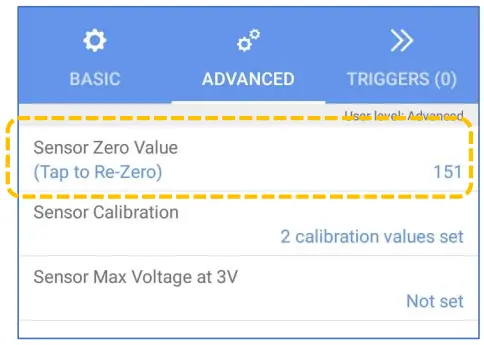
The logger can apply an offset to compensate for barometric pressure, thus giving a pressure reading relative to atmospheric pressure. The sensor is required to be re-zeroed to the local atmospheric pressure prior to use (refer to the IDT app user guide for guidance). - Vented gauge’ type pressure sensors that are pre-wired to a connector that is compatible with the Multilog IS. HWM can also supply consumables (e.g., desiccant).
 The vented gauge type sensor is required for certain applications of the logger.
It provides automatic compensation for atmospheric pressure changes. This sensor will include an internal vent-tube which enters a ‘vent break-out adaptor’ at some point on the cable. The adaptor includes a ‘vent’ port for the attachment of further tubing (with a desiccant for drying the air, to prevent damage to the sensor). The desiccant must be changed periodically during routine maintenance of the equipment.
The most common use of the ‘vented gauge’ type of pressure sensor is for applications requiring measurement of shallow fluid depths via the use of a submersible pressure / depth sensor.
4.9 (RTD TEMP) TEMPERATURE SENSOR
The logger may include one or more interfaces (up to 4) for the attachment of an RTD type temperature sensor (Resistance Temperature Detector).
The interface will be labelled as:
RTD (TEMP)
The IDT app will refer to the interface as one of:
Pressure1, Pressure2, Pressure3, Pressure4.
RTD (Resistance Temperature Detector) sensors have a resistivity that is dependent on their temperature. The RTD sensor is passive and therefore usually classed as simple apparatus for ATEX purposes. The logger temporarily applies an excitation current to the sensor whilst making a temperature measurement.
4.10 ANALOGUE CURRENT INPUT (4 to 20 mA) SUPPORT
When the appropriate interface is fitted, the logger supports a general-purpose 4 to 20 mA input. This interface is suitable for connection to a sensor that employs a widely used analogue signalling interface for sensor equipment, 4-20mA current output.
Available options are:
- 4 to 20 mA (PASSIVE).
(The logger provides a current path for sensor equipment that has its own power source). - 4 to 20 mA (ACTIVE).
(The logger provides a limited current 24V power feed for sensor equipment to use, in addition to a current path for the output signal of the attached sensor).
Active 4-20ma interfaces will require the FTT expansion board to be included.
The PASSIVE interface will be labelled as one of the following: - SINGLE PASSIVE 4-20mA
- DUAL PASSIVE 4-20mA ; 2 channels are present on a connector.
The IDT app will refer to the passive interface as one of: 4-20mA1, 4-20mA2.
The ACTIVE interface will be labelled as one of the following: - SINGLE PASSIVE 4-20mA
The IDT app will refer to the active interface as one of: 4-20mA3, 4-20mA4.
Some sensors are available which combine 4-20mA signalling with an out-of-band signalling on the same wires. (e.g., HART protocol).
The logger supports only the 4~20mA channel on these types of sensors.
During setup, IDT requires two datum points to be entered. These are the expected values (of the physical parameter being measured) when the sensor is at its minimum and maximum range (4mA and 20mA respectively).
Refer to the sensor data sheet for these values.
4.11 ANALOGUE VOLTAGE INPUT SUPPORT
When the appropriate interface is fitted, the logger supports a general-purpose d.c. signal voltage input. This interface is suitable for connection to sensor that employ a widely used analogue signalling interface for sensor equipment, d.c. voltage output.
Available options are:
- 0 to 1 volt (d.c.).
- 0 to 10 volts (d.c.).
The interface will be labelled as one of the following: - SINGLE 0-1V
- DUAL 0-1V ; 2 channels are presented on a connector.
- SINGLE 0-10V
- DUAL 0-10V ; 2 channels are presented on a connector.
The IDT app will refer to the interface as one of:
0-1V 1, 0-1V 2, 0-10V 1, 0-10V 2.
During setup, IDT requires two datum points to be entered. These are the expected values (of the physical parameter being measured) when the sensor is at its minimum and maximum range, 0v and 1v (or 10v) respectively). Refer to the sensor data sheet for these values.
4.12 RADARSENS INTERFACE
The logger may be fitted with a RadarSens interface. This interface supports connection of a HWM RadarSens sensor.
The interface will be labelled as one of the following (or similar):
- RADARSENS.
The IDT app will refer to the interface using the following terms: - RadarSens Measure ; Distance measurement
- RadarSens Temp ; Temperature measurement (internal to sensor)
- RadarSens Intensity ; Radar reflection strength (peak received by the sensor)
The logger provides power and communications to the sensor, which measures distance to a fluid surface. The logger can also derive (by calculation) a variety of other measurements, if the installer provides additional information. For example, the logger can calculate water depth if the installer supplies the distance of the sensor from the bottom of the water channel. It can similarly derive flow rates through open channels or weirs if setup includes the relevant dimensions.
The direct measurement channel and any derived measurement channels each occupy a logical channel, containing datapoints for sending to the server. (See also section 2.6).
4.13 SONICSENS3 (ULTRASONIC) INTERFACE
The logger may be fitted with a SonicSens3 interface. This interface supports connection of a HWM SonicSens3 Ultrasound sensor. Up to three SonicSens3 sensors can be supported.
The interface will be labelled as one of the following (or similar):
- SONICSENS3 (ULTRASONIC). The IDT app will refer to the interface as one of:
- SonicSens Measure [n] ; Distance measurement
- SonicSens Temp [n] ; Temperature measurement (internal to sensor)
- SonicSens Qual [n] ; Sensor data quality (HWM use only)
Where [n] is 1, 2, or 3. When the 2 nd or 3 rd interfaces are present, it will require the FPS expansion board to be included.
The logger provides power and communications to the sensor, which measures distance to a fluid surface. The logger can also derive (by calculation) a variety of other measurements, as long as the installer provides additional information. For example, the logger can calculate water depth if the installer supplies the distance of the sensor from the bottom of the water channel. It can similarly derive flow rates through open channels or weirs if setup includes the relevant dimensions.
The direct measurement channel and also any derived measurement channels each occupy a logical channel, containing datapoints for sending to the server. (See also section 2.6).
4.14 SDI-12 INTERFACE
When the appropriate option is fitted, the logger provides support for an SDI-12 interface. This interface requires the UCOM expansion board to be included, along with an SDI-12 module; up to 2 modules may be fitted.
The interface provides power to the sensor. Various voltages are available (see below);
Refer to the logger interface label for the feed voltage option fitted.
Note: The voltages listed on the label are nominal; refer to the ATEX parameter tables in the safety supplement (provided with the unit) for actual values.
The interface will be labelled as one of the following:
- SDI-12 (7V5)
- SDI-12 (9V5)
- SDI-12 (12V)
The IDT app will require two selections to pick the interface. It will refer to it as a composite of an input sensor and an interface: - Input sensor: Serial [n] ; where [n] is in the range of 1 ~ 16.
- Interface
o 1 – SDI12 (7V5) ; module fitted in expansion slot 1
o 1 – SDI12 (9V5) “
o 1 – SDI12 (12V) “
o 2 – SDI12 (7V5) ; module fitted in expansion slot 2
o 2 – SDI12 (9V5) “
o 2 – SDI12 (12V) “
The SDI-12 interface provides the ability for the logger to link to intelligent sensor equipment via an industry-standard serial communications interface. It operates at a fixed speed of 1200 baud. The attached equipment may have one or more sensors.
Note: Ensure the attached sensor has the SDI-12 protocol selected, otherwise communications will fail.
Using the SDI-12 protocol, the logger can make a request for a measurement to the attached equipment. The attached equipment responds when the measurement has been obtained. The logger can temporarily power the equipment just before a measurement is required and whilst waiting for a response.
Obtaining data begins by the logger requesting a measurement (sending an “M” command or a “C” command).
Some sensor equipment will send multiple items of measurement data as a block (e.g., one piece of equipment may include several sensors). The setup of the logger can use a “Reading n” parameter as an index to select the required data from the block. The sensor equipment will have an address that the logger must use when communicating with it. Setup of the Multilog IS should therefore include the relevant addresses, commands, and indexes that are required to start the measurement and then select the specific data item required; it can then obtain the channel datapoints. Data from the SDI-12 sensor always takes the format of a floating-point number using ASCII characters. The logger reads the data and converts it into a more compact 16-bit format for storage.
Obtaining measurements is done via the appropriate SDI-12 driver, and the obtained data-stream will then behave like any other; it will require similar setup for the channel to describe what the data actually represents.
The SDI-12 interface includes a power feed to the sensor. Most sensor equipment is powered down in between the logger’s set measurement times, in order to conserve power. However, the equipment may take some time to power up and be able to take measurement requests. This duration can be set in the SDI-12 channel setup using the “Pre-power duration” setting.
Refer to the IDT user-guide for guidance on how to set up the SDI-12 driver parameters. Refer also to the documentation of the SDI-12 equipment regarding addresses, commands, and indexes required to obtain the required data.
4.15 RS485 INTERFACE (MODBUS)
Where the appropriate option is fitted, the logger provides support for a RS485 interface. This interface requires the UCOM expansion board to be included, along with an RS485 module; up to 2 modules may be fitted.
The interface provides power to the sensor. Various voltages are available (see below);
Refer to the logger interface label for the feed voltage option fitted.
Note: The voltages listed on the label are nominal; refer to the ATEX parameter tables in the safety supplement (provided with the unit) for actual values.
The interface will be labelled as one of the following:
- SDI-12 (7V5)
- SDI-12 (9V5)
- SDI-12 (12V)
The IDT app will require two selections to pick the interface.
It will refer to it as a composite of an input sensor and an interface: - Input sensor: Serial [n] ; where [n] is in the range of 1 ~ 16.
- Interface
o 1 – RS485 (7V5) ; module fitted in expansion slot 1
o 1 – RS485 (9V5) “
o 1 – RS485 (12V) “
o 2 – RS485 (7V5) ; module fitted in expansion slot 2
o 2 – RS485 (9V5) “
o 2 – RS485 (12V) “
The RS485 interface provides the ability for the logger to link to intelligent sensor equipment via an industry-standard serial communications interface. The attached equipment may have one or more sensors.
Multilog IS supports several protocols over the RS485 link, including: - Modbus RTU
- Modbus ASCII
- Topwin
Note: The frame format and encoding of the message differs between protocols. Ensure the correct Modbus protocol is selected for the attached sensor equipment, otherwise communications will fail.
Modbus is a protocol which the logger uses, operating as the master device. It sends setup instructions and other information to the attached sensor equipment (which operates in slave mode). The protocol includes the ability to address each register in order to read and (depending on the attached unit) write to the registers. Measurement results are made available to the logger by reading them from specific registers in the sensor equipment over the Modbus link.
The sensor equipment will have an address that the logger must use to identify it when communicating. The setup of the Multilog IS should therefore include the sensor address as well as the register access details (function code, start register address). The quantity of registers to be read will depend on the format of the data within the sensor registers. The logger can handle multiple formats of numeric data (e.g., 16-bit signed, 16-bit unsigned, float, double); however, the expected data format must be specified in the logger setup; this will ensure that the required number of registers are read and that the data is correctly interpreted by the logger. (See IDT app user-guide for details). The read data can then be used to obtain the channel datapoints. Obtaining measurements is done via the Modbus driver, and the obtained data-stream will then behave like any other; it will require similar setup for the channel to describe what the data actually represents. The RS485 driver includes a power feed to the sensor. Most sensor equipment is powered down in between the logger’s set measurement times, in order to conserve power. However, the equipment may take some time to power up and be able to take measurement requests. This duration can be set in the RS485 channel setup using the “Pre-power duration” setting.
When setting the logger for use with your sensor, usually the “generic” settings are suitable. However, some modification of the logger operation is required for certain types of sensor equipment in order to get the best out of them. IDT provides a control to select specific sensors from a list. Once chosen, the logger will handle any peculiarities of the behaviour of the sensor, its protocol, or additional needs for the measurement being taken (e.g., additional exchanges of information between the logger and the sensor equipment). The RS485 / Modbus setup screen in IDT gives access to various additional parameters related to the protocol, including bus-speed and timers.
Refer to the IDT app user-guide regarding how to set up the RS485 / Modbus interface.
This must be read in conjunction with the user-guide of the equipment that is being attached; this will provide information on the measurements available from the sensor equipment, which registers contain the results (and the numeric format of the data), and how to initiate the read of a register to obtain the required data.
4.16 DIGITAL SENSOR INTERFACE
Where the appropriate option is fitted, the logger provides support for selected HWM digital sensors. (Up to 4 interfaces can be supported).
Available options are:
- 4-pin interface for selected HWM sensor types
- 6-pin interface for selected HWM sensor types.
Compatible HWM sensors for the 4-pin interface include: - SpillSens (SpillSens is a digital float angle sensor.
The logger can be configured to trigger at certain angles to produce behaviour similar to a programmable angle float switch).
Compatible HWM sensors for the 6-pin interface include:
- (Reserved for future use).
The interface will be labelled as one of the following (or similar): - DIGITAL SENSOR
The IDT app will refer to the interface as one of the following: SpillSens1, SpillSens2, SpillSens3.
Refer to the IDT app user-guide regarding how to set up the interface for use with the supplied sensor. This must be read in conjunction with any user-guide available for the sensor.
INSTALLATION
5.1 SUMMARY OF INSTALLATION STEPS
- Check the logger is suitable for use at the installation site (e.g., ATEX markings), that you have the required sensors and that these are suitable for use at the installation site (e.g., check suitable ATEX markings are present).
Check port parameters permit interconnection in an ATEX environment. - Check all cables are of a suitable length.
- Swipe the logger to activate Bluetooth ® communications. Begin communications between the IDT app (on the mobile phone) and the logger.
- Update the logger firmware (if required) on the main board or any internal modules. (Refer to the IDT manual for guidance; consider downloading any existing data from the logger prior to upgrade).
- Use IDT to check or modify existing logger settings: (Refer to the IDT user-guide for guidance).
o Program a local time-zone into the logger.
o Set timing intervals for making measurements (sample interval and log interval). They should be configured to suit your use of the device and any specific logging requirements. - Channel settings for producing datapoints from each interface.
Configure the logger interfaces to match the sensor or other equipment that the logger connects to.
(There will be considerable variation in the requirements for this, depending on the interfaces that are fitted to the logger and the sensors or other equipment being used). - Map the sensor to appear as an output data channel within the logger.
This is an identifier for the datapoint stream that is used when uploading the logged measurement data to the server.
▪ The numeric data-stream must be characterised as to what the
numbers represent (i.e., physical parameters).
▪ Apply any required statistical functions to the background measurement samples in order to produce logged data-points (saved values).
o Where required, undertake the setup of any additional options related to the channel. (e.g., add an initial meter reading, pulse replication setting, sensor calibration; these will be dependent on sensor and logger use).
(Refer to the IDT user-guide for guidance regarding and any additional settings related to an interface).
o Setup any required trigger conditions for activating a logger alarm messages and also conditions for the alarm to clear.
o Attach the sensors and (if required) re-calibrate / re-zero them.
o Test the logger sensors are functioning correctly.
(Some can be done pre-installation; others post installation).
o Set the logger up for data delivery to the server.
Call-in times.
Server contact details.
o Check / modify the communications settings of device, as required:
Call-in settings,
Data Destination settings,
SIM settings (access parameters for the network),
Modem settings (Cellular Network technology).
• Install (position and connect) the logger and sensors.
• Install (position and connect) the antenna.
Test cellular communications performance.
• Verify the setting changes have been saved prior to leaving site.
• Ensure details of the site of logger deployment are recorded.
(The administration for the server could be handled by office staff, or the installer could use the HWM Deployment app).
5.2 INSTALLING THE LOGGER
The logger must be mounted in a suitable location where the sensors to be attached can reach their intended installation points. Position loggers, sensors, and antenna away from sources of electrical interference such and motors or pumps.
Refer to the orientation shown in the diagram in section 2.1; The logger should be installed as shown for optimum battery performance.
Check for any access issues for using on-site communications; Refer to section 3.3 for guidance.
Use the keyhole mounting holes to fix the logger in position. Anti-tamper seals can also be used if required to bear witness if anyone has interfered with the installation by disassembling the logger. (See diagram in in section 2.1)
Ensure the antenna can be mounted in a suitable location where the radio signal will be of sufficient strength to call into the cellular network.
The cables should be routed and secured without causing any hazards. Do not allow any equipment to rest on cables or connectors as crush damage can result.
Note: Certain sensors have their own instructions regarding installation requirements and their configuration using IDT.
Follow the additional guidance where available.
Where required, insulate any water-filled tubing connected to pressure transducers to protect them from frost. Insulating pipe covers can be supplied upon request at additional cost or sourced locally from a hardware store.
5.2.1 Verification of the configuration.
Prior to leaving site, check the program settings of the logger are correct.
5.3 POWER USE CONSIDERATIONS / EXTERNAL BATTERY OPTION
The logger supplied may have an “EXT POWER” connector fitted for the connection of an external battery; this is for providing additional power to the logger.
(The connector is an available option. The additional battery power may be required in order to increase the length of service of the logger. Larger configurations of logger or the use of certain sensors can also cause additional power to be required from the external battery pack).
Batteries are heavy devices. When positioning the battery, ensure that it is not crushing any cables or tubes within the installation. Alternatively, mount it in a suitable location using the mounting holes.
For optimal battery life, respect any orientation arrows that may be on the battery pack.
Attach the battery to the logger ensuring that the connector is fully located, so that it is watertight. Similarly, ensure the battery-side cable end is watertight.
Only fit an ATEX approved 10.8V battery provided by HWM that has been approved for use with Multilog IS.
 The power requirements of the logger depends on quantity of interfaces fitted to the model, the power consumption of attached sensors, and the workload of the unit (e.g., Measurement sample intervals and number of call-ins per day; parameters that can be modified by an installer, who should set the logger activity to be the minimum that the application requires).
The following guidance may be used, but where in doubt it is advisable to discuss the expected service life of the unit with your HWM representative prior to placing your order. Additional power from an external battery is required for any of the following:
- Whenever IDT input Pulse 07 (or upwards) is included in the logger (e.g., for pulse replication purposes, or if the logger is fitted with more than 3 connectors for FLOW interfaces / 3 pulse-pairs).
- When the logger is fitted with more than 1 SonicSens3 interface.
- When the logger is fitted with any ACTIVE 4-20mA interfaces.
- When the logger is fitted with any RS485 interfaces.
- When the logger is fitted with any SDI-12 interfaces.
- When the number of call-ins exceeds an average of 3 per day. (Sending of an alarm and alarm clear messages immediately on their occurrence should be included).
5.4 INSTALLING THE ANTENNA AND TESTING CELLULAR COMMUNICATIONS
Only use HWM-provided antenna for use with your logger, to ensure the radio interface meets approvals requirements (safety, etc).
The logger family has two antenna connector options:
- Antenna (plastic “Bulgin” style connector shell).
- Antenna (metal “FME” style connector).

An antenna with the appropriate connector should be selected and attached, tightening finger-tight only. No sharp bends should exist in the cable routing of the antenna.
If possible, avoid locations where the antenna could be adversely affected (e.g., by an occasional flood condition).
IDT should be used to check that the logger can connect to the cellular network and that the antenna is in the optimal position for the site.
- Choose a suitable antenna for the installation and decide on its initial position.
- Determine the network technology being used and the appropriate signal quality limits that should be used (refer to the IDT user-guide).
- Perform Network Signal tests to confirm the logger connects to the mobile network and find the best location of the antenna.
- Perform test calls to confirm the logger can communicate with the DataGate server via the internet and (if required) SMS.
(Details of use of IDT for making these tests are provided in the IDT app user-guide).
Trouble-shoot a test-call failure if required, using the advice in the IDT app user-guide.
Further information is given in the HWM Antenna Installation Guide (MAN-072-0001), and on the webpage https://www.hwmglobal.com/antennas-support/
Some general advice is given below:
Monopole Antenna
For most installations, a monopole antenna will give acceptable performance.
Installation Considerations:
- Always comply with any installation restrictions as per warnings in the documentation supplied.
- The antenna has a magnetic base to be used for mounting. For optimum performance, the antenna requires a “ground plane” (metal surface) at its base.
- When installing the antenna in large underground chambers it should be positioned close to the surface.
- Ensure that any chamber lid will not interfere with the antenna or cables when being opened/closed.
- This antenna is vertically polarised, it should always be installed in the vertical orientation.
- Never bend the radiating element of the antenna.
- The antenna can also be attached to an installation bracket mounted to an existing marker post.
- Where an antenna is held in place by magnets, ensure the weight of any cables does not excessively load the magnet so as to detach it from the installed location.
- Do not allow any equipment to rest on the antenna connector as crush damage to the connector or antenna cable can result.
For other antenna options and additional installation guidelines, refer to the documents available on the HWM support webpage:
https://www.hwmglobal.com/antennas-support/
Troubleshooting a Call Test failure
There are a number of reasons why a Call test may fail.
The following points should be checked before calling HWM support for assistance: –

| Possible Problem | Solution |
| Network Busy due to excessive traffic. Commonly occurs around schools and at peak travel times. | Retry the test after a few minutes. |
| Network signal not available at your location. Not all Cell masts carry data traffic | Relocate the logger to an area that has a data service or change to a different network provider. |
| Network signal not strong enough. You need a CSQ (reported by the Call test) of at least 8 for reliable communications. | Relocate the antenna if possible or try alternative antenna configurations. |
| APN settings incorrect. | Check with your network operator that you have the correct settings for your SIM. |
If you continue to experience problems with communication, you may need to check the network coverage in your location.
CONNECTING SENSORS (AND OTHER DEVICES)
![]() Warning:
Warning:
This equipment must be installed by a person who is competent to make any required electrical connections in a manner suitable for the installation site. Care must be taken where the site has a requirement for ATEX or other Intrinsically Safe standards to be met.
When installing the Multilog IS within an ATEX environment, all attached sensors and installation cables must meet ATEX requirements.
Check the cable connector is made of a plastic material, not metallic, to prevent premature wearing of the logger connector during repeated connect / disconnect cycles.
The Multilog IS logger is available with many sensor options. Sensors provided by HWM will include a cable with a suitable connector for the Multilog IS. If you have a need for a sensor not currently supplied by HWM, discuss your requirements with your HWM representative.
For some installations the logger must interconnect to equipment already on site (e.g., Flow meters), which requires a suitable cable for attachment. The Multilog IS data logger must only be used in conjunction with HWM connection cables. Discuss your cable needs with your HWM representative to confirm availability.
Note that long data connections should always be made using screened cable. The use of a screened cable will ensure maximum rejection of interference from outside sources.
Always use a common ground point without creating ground loops.
Connect any supplied cable to the sensor side first (if required). Then connect the logger side.
The connector (3-pin, 4-pin, or 6-pin) should be rotated until it is possible to push it into location, and then rotate the front of the connector until it “clicks” into place. This will secure the connector and it will also become water-tight.
If a sensor is removed from the Multilog IS, be sure to protect the connector with a water-tight cover to ensure the contacts remain free of dirt and moisture.
Ensure the sensor connector is also kept clean.

![]() Warning: Before connecting any sensor to the logger ensure you have correctly identified the connector to which it belongs.
Warning: Before connecting any sensor to the logger ensure you have correctly identified the connector to which it belongs.
For installation in an ATEX environment, check that the ATEX port parameters of the logger and sensor are suitable for interconnection.
6.1 FLOW (PULSE INPUT) INTERFACE
|
Logger bulkhead connector pinout : FLOW (Pulse Input) |
|||
| A / 1 | B / 2 | C / 3 | D / 4 |
| —– | Pulse Input Ch1 | Gnd | Pulse Input Ch2 |
To connect the logger to the equipment that produces meter pulses, an appropriate cable is required.
Connect the meter equipment end of the cable. Then connect the logger end of the cable to the to the relevant logger interface.
The function assigned to each pin of the connector depends on settings of the logger.
(Refer to section 4.6 and the IDT app user-guide for general guidance / further details regarding setting the pulse input channels and the configuration of their operation).
Following connection, the logger must be correctly set up to interoperate correctly with the attached equipment to give the desired data channel output(s).
Identifying Multiple Interfaces:
For a pulse input, the interface number can be identified or confirmed by shorting and opening a pulse ‘input’ wire to the ‘gnd’ wire whilst observing the channels in the hardware test screen of IDT.
The circuit can be identified by the input state alternating between “O” and “X” or between “<<” and “>>”).
6.2 STATUS INPUT INTERFACE
|
Logger bulkhead connector pinout : FLOW (Pulse Input), when used as a Status Input. |
|||
| A / 1 | B / 2 | C / 3 | D / 4 |
| —– | Pulse Input Ch1 (or Status Input 1) |
Gnd | Pulse Input Ch2 (or Status Input 2) |
Note: The interface will be labelled “Dual Unidirectional FLOW”, “Single Bidirectional FLOW”, (or similar); One or more pins on a FLOW (pulse input) interface can (optionally) be re-purposed to become a Status Input.
For an introduction to the use of Status inputs, refer to section 4.6.2.
To connect the logger to the other equipment, an appropriate cable is required.
Connect the far end of the cable to the equipment being monitored. Then connect the logger end of the cable to the to the relevant logger interface.
Refer to IDT app user-guide regarding how to assign the use of the ‘pulse input’ pin to become a Status input. Also, it will describe the subsequent setup required for use of the status input. The logger must be set up to monitor the attached equipment, give the desired functionality, and produce data channel output(s).
Identifying Multiple Interfaces:
For a status input, the interface number can be identified or confirmed by shorting and opening the used ‘pulse input’ wire to the ‘gnd’ wire whilst observing the channels in the hardware test screen of IDT.
The circuit can be identified by the input state alternating between “O” and “X”).
6.3 STATUS INPUT INTERFACE / USED AS A TAMPER ALARM.
|
Logger bulkhead connector pinout : FLOW (Pulse Input), when used as a Status Input. |
||||
| A / 1 | B / 2 | C / 3 | D / 4 | |
| (1) | —– | Pulse Input Ch1 | Gnd | Pulse Input Ch2 (or Status Input 2; used for Tamper detection) |
| (2) | —– | Pulse Input Ch1 (or Status Input 1; used for Tamper detection) |
Gnd | Pulse Input Ch2 |
Refer to sections 6.1 regarding FLOW inputs and 6.2 Status inputs.
The Multilog IS allows the 2 pulse inputs in a FLOW connector to be split, in order to implement a Uni-directional FLOW channel plus a Tamper-alarm (e.g., to detect cable detachment). The two possible pinout options are shown in the table above.
To connect the logger to the other equipment (usually a meter), an appropriate cable is required.
In addition, the meter must support the tamper detection circuit by internally connecting the Tamper circuit to form a loop. The normal condition is for the tamper circuit to have a current path (loop) present between the two wires (Status and Gnd).
If the cable is detached from the logger or from the meter, the logger will sense a break in the tamper loop (no current flow possible) and the logger can (when appropriately setup) notify the server of a Tamper alarm.
6.4 STATUS (DIGITAL OUTPUTS) / INTERFACE
|
Logger bulkhead connector pinout : Status Output |
|||
| A / 1 | B / 2 | C / 3 | |
| Dual Status Output | Output Ch1 | Output Ch2 | Gnd |
| Single Status Output | Output Ch1 | —– | Gnd |
Multilog IS has two versions of Status (Digital Output) connector available (see above).
Note: The interface will be labelled “Dual Status Output”,
“Single Status Output”, (or similar).
To connect the logger Digital outputs to the other equipment, an appropriate cable is required.
Connect the output end of the cable as required by the other equipment. Then connect the logger end of the cable to the to the relevant logger interface.
Following connection of the equipment, the logger must be set to give the desired functionality. Refer section 4.7 for details of the possible use of these outputs.
Refer to the IDT app user-guide for setup guidance.
Identifying Multiple Interfaces:
For a status output, the interface number can be identified or confirmed by creating a temporary trigger and action within IDT.
The circuit can be identified by the output state alternating between closed and open when the output changes in response to being triggered and then cleared from being triggered. This can be inspected by using an ohm meter between the output and gnd pins).
6.5 EXTERNAL PRESSURE (FOR PRESSURE OR DEPTH SENSORS)
| Logger bulkhead connector pinout : External Pressure (4-Pin & 6-Pin) | (6 Pin only) | |||||
| A / 1 | B / 2 | C / 3 | D / 4 | E / 5 | F / 6 | |
| V (+) ; (PWR) | V (+) ; (Signal) | V (-) ; (PWR) | V (-) ; (Signal) | Screen | Screen | |
Multilog IS has two versions of the input available, 4 or 6 pin, (see above).
Note: The interface will be labelled
“EXTERNAL PRESSURE (4-PIN)” or
“EXTERNAL PRESSURE (6-PIN)”.
The logger temporarily applies power to the sensor just before making a measurement.
Only use Intrinsically Safe sensors.
For sealed type pressure (or depth) sensors, the sensor will be wired directly to the connector, as shown opposite.

For vented gauge type pressure (or depth) sensors, the sensor will include an External Venting Interface adaptor box, similar to the kit shown opposite.
The connection to the logger is wired only.
Tubing is required to connect the sensor to an air path at atmospheric pressure via the venting interface and also a breather tube filled with desiccant.

 Tubing (of the required length) should be joined to the vent port of the venting interface. Then attach the breather to the other end of the tube. Add desiccant to the breather and mount in a dry area. The tubing should be attached to a vented container which is filled with a desiccant to keep the air dry. Mount the breather in a dry area.
Mount the venting interface in a suitable location where the cable can reach the logger and the sensor can be put into position.
A depth sensor should be weighted down or mounted securely at the bottom of the water channel, using a fixture (e.g., a carrier plate or anchoring bracket) if required.
Prior to immersing in water, the sensor should be re-zeroed to atmospheric pressure (refer to the IDT app user guide). The cable should also be secured in place to prevent moving water from acting on the cable to pull the sensor out of position or stress any connections.
Where a pressure transducer has a threaded end for connection to the pressure measurement point, fittings may be required to modify the connection (e.g., a quick-release connector for connection to a hose).

Assemble any fittings prior to connecting to the logger. Straight or elbow styles of coupling kits are available.

Confirm the logger has the appropriate interface for the pressure or depth sensor. Then connect the sensor to the relevant logger interface. Do not connect the sensor to the measurement point before going through the calibration process and re-zero (to local atmospheric pressure) process, if required.
For a pressure transducer, attach to the measurement point and (if applicable) bleed any connecting hose.
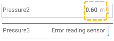
Identifying Multiple Interfaces: For a pressure input, the interface number can be identified or confirmed by plugging in and then unplugging the sensor whilst doing a hardware test.
The circuit can be identified by the output that changes value between when the sensor is plugged in and when it is unplugged.
It may also show an error when unplugged).
Note: Any RTD (Temp) interfaces will also be shown as a Pressure channel in IDT.
Calibration Process:
Prior to using the sensor, the logger and sensor must be calibrated to give correct readings.
Two methods exist.
- Calibration using calibration values shown on the cable. Add the details from the calibration label on the cable into the logger using IDT.
- Regular calibration method (apply pressure and set calibration values in a table). Refer to the IDT app user-guide for both methods.

Re-Zero Process:
Pressure and depth sensors can be re-zeroed to local atmospheric pressure prior to being used.
This must be done with the sensor exposed to atmospheric air.
Follow the instructions in the IDT user-guide for guidance on how to undertake this operation.
 After following the calibration process and re-zero process, the transducer can be located at (or fitted to) its measurement point.
The logger must be correctly set up to make measurements from the sensor. Refer to the IDT app user-guide for general guidance / further details.
6.6 (RTD TEMP) TEMPERATURE SENSOR
| Logger bulkhead connector pinout : RTD (TEMP) (4-Pin & 6-Pin) | (6 Pin only) | |||||
| A / 1 | B / 2 | C / 3 | D / 4 | E / 5 | F / 6 | |
| V (+) ; (PWR) | V (+) ; (Signal) | V (-) ; (PWR) | V (-) ; (Signal) | Screen | Screen | |
Multilog IS has two versions of the input available, 4 or 6 pin, (see above).
Confirm the logger has the appropriate interface for the supplied RTD sensor.
Install the RTD sensor at the measurement position. Connect the RTD sensor to the logger.
Ensure the logger is correctly set up to make measurements from the attached sensor.
Refer to the IDT app user-guide for general guidance / further details.
Identifying Multiple Interfaces:
For a pressure input (being used with a RTD temperature sensor), the interface number can be identified or confirmed by plugging in and then unplugging the sensor whilst doing a hardware test.
The circuit can be identified by the output that changes value between when the sensor is pluggedin and when it is unplugged.
It may also show an error when unplugged).
 Note: Any RTD (Temp) interfaces will be shown as a Pressure[n] channel in IDT.
6.7 ANALOGUE CURRENT INPUT (4 to 20 mA)
|
Logger bulkhead connector pinout : Single 4-20mA (Passive) |
|||
| A / 1 | B / 2 | C / 3 | D / 4 |
| —– | 4-20mA Loop (+) Ch1 | —– | 4-20mA Loop (-) Ch1 |
|
Logger bulkhead connector pinout : Dual 4-20mA (Passive) |
|||
| A / 1 | B / 2 | C / 3 | D / 4 |
| 4-20mA Loop (-) Ch2 | 4-20mA Loop (+) Ch1 | 4-20mA Loop (+) Ch2 | 4-20mA Loop (-) Ch1 |
|
Logger bulkhead connector pinout : Single 4-20mA (Active) |
|||
| A / 1 | B / 2 | C / 3 | D / 4 |
| V (+) ; (PWR) | 4-20mA Loop (+) Ch1 | 4-20mA Loop (-) Ch1 | Gnd ; (PWR) |
The Multilog IS has three different versions of this interface available (see above). (Refer also to section 4.10). The connector used for Active 4-20mA are of a different size to the one used for Passive 4-20mA.
Confirm that your sensor uses 4-20mA signalling and whether an active or passive type of interface is required; confirm the logger has the appropriate interface. To connect to the logger, the sensor must have a cable with an appropriate connector.
Follow the installation guidance within any documentation supplied with the sensor.
Connect the sensor equipment end of the cable. Then connect the logger end of the cable to the to the relevant logger interface.
Following connection, the logger must be correctly set up to make measurements from the attached sensor. The channel will require setup of calibration factors for the interface and additional setup to define what the sensor data actually represents.
Refer to the IDT app user-guide for guidance / further details.
Identifying Multiple Interfaces:
Any connector labelled as “ … (Active)” will be numbered as input channel 3 or 4.
Any connector labelled as “ … (Passive)” will be numbered as input channel 1 or 2.
For a 4-20mA input, the channels can be identified by plugging in and then unplugging the sensor (be sure to use either active or passive, to match the connector label) whilst doing a hardware test.
The circuit can be identified by the output that shows a change in value between when it is plugged in and when it is unplugged.
It may also show an error when unplugged.
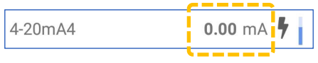
6.8 ANALOGUE VOLTAGE INPUT (0-1 V, 0-10 V)
|
Logger bulkhead connector pinout : Single 0 – 10V & Single 0 – 1V |
|||
| A / 1 | B / 2 | C / 3 | D / 4 |
| —– | V (+) Ch1 | —– | V (–) Ch1 |
|
Logger bulkhead connector pinout : Dual 0 – 10V & Dual 0 – 1V |
|||
| A / 1 | B / 2 | C / 3 | D / 4 |
| V (–) Ch2 | V (+) Ch1 | V (+) Ch2 | V (–) Ch1 |
The Multilog IS has four versions of interface available (see above).
(Refer also to section 4.11).
Confirm that your sensor uses d.c. voltage signalling and the output voltage range.
Confirm the logger has the appropriate interface. To connect to the logger, the sensor must have a cable with an appropriate connector.
Follow the installation guidance within any documentation supplied with the sensor.
Connect the sensor equipment end of the cable. Then connect the logger end of the cable to the to the relevant logger interface.
Following connection, the logger must be correctly set up to make measurements from the attached sensor equipment. The channel will require setup of calibration factors for the interface and additional setup to define what the sensor data actually represents. Refer to the IDT app user-guide for guidance / further details.
Identifying Multiple Interfaces:
For a voltage signal input, the interface number can be identified or confirmed by plugging in and then unplugging an appropriate sensor whilst doing a hardware test.
(Be sure to use a sensor with a 0-1V output where needed).
The circuit can be identified by the output that shows a change in value between when it is plugged in and when it is unplugged).
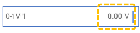
6.9 RADARSENS SENSOR:
|
Logger bulkhead connector pinout : RadarSens |
|||||
| A / 1 | B / 2 | C / 3 | D / 4 | E / 5 | F / 6 |
| V (+) (SS3_PWR) | Gnd | SS3_CLK | Gnd | SS3_Data | Gnd |
RadarSens is a sensor available from HWM that uses radar to measure the distance from the sensor to a water surface. An installation bracket is required to hold the sensor in a fixed position. Further details are given in the RadarSens user guide. (Refer also to section 4.12 and the IDT app user guide).
Confirm the logger has the appropriate interface for the RadarSens sensor. Connect the sensor to the logger.
Following connection of the sensor, it must be correctly installed at the required measurement position and then set up.
RadarSens can be used to produce more than one data channel. For example, distance measurements can also be used by the logger to derive other parameters for logging, such as water depth or water flow from a weir. Each data channel will consume one of the available channels of the Multilog IS.
6.10 SONICSENS3 SENSOR:
|
Logger bulkhead connector pinout : SonicSens3 (Ultrasonic) |
|||||
| A / 1 | B / 2 | C / 3 | D / 4 | E / 5 | F / 6 |
| V (+) (SS3_PWR) | Gnd | SS3_CLK | Gnd | SS3_Data | Gnd |
SonicSens3 is a sensor available from HWM that uses ultrasound to measure the distance from the sensor to a surface (typically a water surface). An installation bracket is required to hold the sensor in a fixed position. Further details are given in the SoncSens 3 user guide. (Refer also to section 4.13 and the IDT app user guide).
Confirm the logger has the appropriate interface for the SonicSens 3 sensor. Connect the sensor to the logger.
Following connection of the sensor, it must be correctly installed at the required measurement position and then set up.
SonicSens3 can be used to produce more than one data channel. For example, distance measurements can also be used by the logger to derive other parameters for logging, such as water depth or water flow from a weir. Each data channel will consume one of the available channels of the Multilog IS.
Identifying Multiple Interfaces:
For a SonicSens 3 input, the interface number can be identified or confirmed by plugging in a sensor and doing a hardware test.
The circuit can be identified by the output that shows a measurement result when it is plugged in and an error message when it is unplugged.
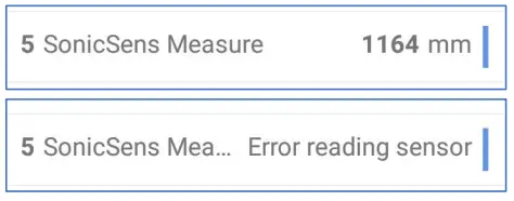
6.11 SDI-12 INTERFACE
|
Logger bulkhead connector pinout : RS485 |
|||
| A / 1 | B / 2 | C / 3 | D / 4 |
| V (+) ; (PWR) | RS485_A | Gnd | RS485_B |
The Multilog IS can provide one of 3 versions of ‘SDI-12’ interface.
Note: The interface will be labelled “SDI-12”, followed by a nominal voltage.
e.g., “SDI-12 (12V)”.
Note: The voltage shown on the label is nominal; refer to the ATEX parameter tables in the safety supplement provided with the unit for reference values. The actual voltage present on the output pins varies, depending on current output.
The logger temporarily applies power to the sensor equipment just before making a measurement.
Important: SDI-12 sensor equipment must not have its own power source. The logger must provide power to it.
Important: Check that the supplied voltage is compatible with the permitted supply voltage range of the attached equipment when it is being used in an ATEX environment.
To connect the logger to the SDI-12 equipment, the equipment must have a cable with an appropriate connector. HWM supplies a variety of sensors suitable for connection to a Multilog IS SDI-12 interface.
Confirm the power requirements (supply voltage) of the equipment to be attached to the logger. Confirm the logger has the appropriate SDI-12 interface, including the voltage of its power feed to the sensor equipment. Check the port parameters are suitable for interconnecting the sensor equipment to the logger.
Connect the SDI-12 sensor to the relevant logger interface.
Note: The SDI-12 connector should be used for point-to-point communications only.
It should not be wired in multi-drop mode (no parallel connections).
Following connection, the logger must be correctly set up to make measurements from the attached sensor. (See section 4.14. Refer to the documentation for the sensor. Refer also to the IDT app user guide).
Where the sensor equipment has multiple items of different data available, the logger can read them, each forming a distinct logger channel.
Note: IDT will refer to the interface as a “Serial n” channel; multiple serial channels may be available for use (Serial1 to Serial4 is typical). This is because each sensor within (or item of data obtained from) the attached intelligent device has to be set up as a distinct logger channel, specifying how to locate the read the data item from the sensor.
Each channel will require additional setup to define what physical parameter the datapoints actually represent, unit of measure, etc.
6.12 RS485 INTERFACE (MODBUS)
|
Logger bulkhead connector pinout : RS485 |
|||
| A / 1 | B / 2 | C / 3 | D / 4 |
| V (+) ; (PWR) | RS485_A | Gnd | RS485_B |
The Multilog IS can provide one of 3 versions of ‘RS-485’ (Modbus) interface.
Note: The interface will be labelled “RS485”, followed by a nominal voltage.
e.g., “RS485 (12V)”.
Note: The voltage shown on the label is nominal; refer to the ATEX parameter tables in the safety supplement provided with the unit for reference values. The actual voltage present on the output pins varies, depending on the current output to the sensor.
The logger temporarily applies power to the sensor equipment just before making a measurement.
Important: RS485 sensor equipment must not have its own power source.
The logger must provide power to it.
Important: Check that the supplied voltage is compatible with the permitted supply voltage range of the attached equipment when it is being used in an ATEX environment.
To connect the logger to the RS-485 / Modbus equipment, the equipment must have a cable with an appropriate connector. HWM supplies a variety of sensors suitable for connection to a Multilog IS RS-485 interface.
Confirm the power requirements (supply voltage) of the equipment to be attached to the logger. Confirm the logger has the appropriate RS-485 interface, including the voltage of its power feed to the sensor equipment. Check the port parameters are suitable for interconnecting the sensor equipment to the logger.
Connect the RS485 / Modbus sensor to the relevant logger interface.
Note: The RS485 connector should be used for point-to-point communications only.
It should not be wired in multi-drop mode (no parallel connections).
Following connection, the logger must be correctly set up to make measurements from the attached sensor. (See section 4.15. Refer to the documentation for the sensor. Refer also to the IDT app user guide).
Where the sensor equipment has multiple items of different data available, the logger can read them, each forming a distinct logger channel.
Note: IDT will refer to the interface as a “Serial n” channel; multiple channels may be shown as available for setup (Serial1 to Serial4 is typical). This is because each sensor within (or item of data obtained from) the attached intelligent device has to be set up as a distinct logger channel, specifying how to locate the read the data item from the sensor.
Each channel will require setup to define what the datapoints actually represent, unit of measure, etc.
Note: Normally a channel should be set to the “generic” intelligent device within the driver. However, certain types of devices may allow or require additional parameter exchange following power-up. The Multilog IS provides additional driver support for a selection of such devices. Select the more specific setting for the driver, if appropriate.
6.13 DIGITAL SENSOR INTERFACE
|
Logger bulkhead connector pinout : DIGITALSENSOR (4-Pin) |
|||
| A / 1 | B / 2 | C / 3 | D / 4 |
| +3V3 ; (PWR) | DATA | GND | CLK |
|
Logger bulkhead connector pinout : DIGITALSENSOR (6-Pin) |
|||||
| A / 1 | B / 2 | C / 3 | D / 4 | E / 5 | F / 6 |
| +3V3 ; (PWR) | CLK | DATA | RDY | GND | —- |
The Multilog IS can provide 2 versions of “Digital Sensor” interface for selected HWM sensor types.
Note: The interface will be labelled
“Digital Sensor (4-pin)”,
“Digital Sensor (6-pin)”.
Before attaching the sensor, confirm the logger has an appropriate interface. Connect the sensor to the logger.
Following connection of the sensor, it must be correctly installed at the required measurement position. The logger should then set up to make the required measurements from the sensor. Refer to the IDT app user-guide for guidance. Also refer to any additional user-guide for the sensor, if applicable, for detailed information and installation instructions.
VIEWING YOUR DATA
The logger usually calls into a server, where the data can be stored. The data for the entire deployment period is linked to the site on which it was deployed. If the logger is removed from the site this should be registered with the DataGate server, as should any subsequent re-deployment of the logger to another site.
Site data is best viewed with the viewing tool (usually a website) linked to the server that is used as the data-store. For certain applications, the viewing tool can display the status of multiple deployed devices simultaneously. Thus, for example, the state of an area of a utility network can be visualised by showing each site, where a logger is deployed, on a map and the current or recent sensor status).
Refer to the appropriate manual or instructions for your viewing tool for guidance.
IDT is not designed to support such fleet-wide views of data. However, the data of the connected logger can be temporarily downloaded to the IDT app. IDT can then be used to view a single logger’s data graphically (whilst it remains connected to the logger via Bluetooth). (Refer to the IDT app user-guide for instructions on how to do this).
TROUBLESHOOTING
The IDT app, the logger, the user and sometimes the server interact with each other.
Any issues should consider all four parts of the system.
Refer to the IDT app user-guide for advice on various problems which can occur with use of the logger.
The data from the logger does not appear on the server:
- Check the settings for the SIM card to access the mobile data network.
- Ensure the logger uses the correct data destination URL and port-number for your server.
- Check call-in times have been set.
- Check antenna is attached and in an OK condition.
Check signal quality and strength parameters are suitable. Re-locate the antenna, if required, or try an alternative type of antenna. - Make a Call Test and confirm OK.
- Ensure your server is correctly configured to receive and present the data.
The logger does not appear on the IDT app: - Check the logger communication is active.
Re-activate the logger communications if it has timed out. - Check with your administrator that your DataGate account gives you permissions to use the logger.
Check with your administrator if the security settings of the logger device are set and that the DataGate account being used in conjunction with the IDT app is set up to allow access to the settings of the logger.
MAINTENANCE, SERVICE AND REPAIR
Unauthorised servicing will void the warranty and any potential liability for HWM-Water Ltd.
9.1 REPLACEABLE PARTS
Antenna
- Only use antenna recommended and provided by HWM.
For details of antenna options and part-numbers to order, refer to the following link: https://www.hwmglobal.com/antennas-support/
Batteries
- Only use batteries and parts recommended and provided by HWM.
- Batteries are only replaceable by a HWM approved service centre or relevantly trained technician. Contact your HWM representative for more details if required.
A battery swap must be accompanied by a reset of power-use counters for the logger to perform normally. - Batteries can be returned to HWM for disposal. To arrange the return, complete the on-line RMA form: https://www.hwmglobal.com/hwm-rma/
Refer to the Safety Warnings and Approvals Information for guidelines of the packing requirements.
SIM-card
- SIM-cards are replaceable by a HWM approved service centre or relevantly trained technician.
- Only use consumable parts recommended and provided by HWM.
9.2 RETURN OF PRODUCT FOR SERVICE OR REPAIR
When returning product for investigation or repair, be sure to follow the instructions of your distributor to document why the product is being returned and provide contact details.
If returning to HWM, this can be done by completing the on-line RMA form: https://www.hwmglobal.com/hwm-rma/
Prior to shipping, put the equipment into Shipping mode (refer to the IDT app userguide for instructions). Refer to the Safety Warnings and Approvals Information for guidelines of the packing requirements.
If soiled, ensure the unit is cleaned with a mild cleaning solution and soft brush, disinfected, and dried prior to shipment. Any cleaning must be done outside of an ATEX environment.
©HWM-Water Limited. This document is the property of HWM-Water Ltd. and must not be copied or disclosed to a third party without the permission of the company. All images, text and designs are protected by international and UK copywrite law and remain the property of HWM-Water. It is against the law to copy or use any of the content from the HWM website or literature without the written consent of HWM-Water.
HWM-Water Ltd reserve the right to vary the specification. MAN-156-0001-B
![]() HWM-Water Ltd.
HWM-Water Ltd.
Ty Coch House
Llantarnam Park Way
Cwmbran
NP44 3AW
United Kingdom
+44 (0)1633 489479
www.hwmglobal.com
Documents / Resources
 |
HWM MAN-156-0001 Multilog IS Certified Logger Built with a Variety of Sensors [pdf] User Guide MAN-156-0001 Multilog IS Certified Logger Built with a Variety of Sensors, MAN-156-0001, Multilog IS Certified Logger Built with a Variety of Sensors, Certified Logger Built with a Variety of Sensors, Built with a Variety of Sensors, Variety of Sensors, Sensors |
References
-
 Convenient Water Delivery Near You | Primo Water Delivery
-
 HWM | Energy Management, Pressure Control, Data Collection, Environmental Monitoring, Leak Detection,
-
HWM | Energy Management, Pressure Control, Data Collection, Environmental Monitoring, Leak Detection,
-
HWM
-
Help and Downloads
-
Service and Warranty Repair Request Form
- User Manual