
BMG-11S Audio Interface Professional Sound Card

Important: The ScucEsic- Shs single USS 20 Type C port an th rea pane
connect your computer using th USS cable provided. Note that OUGEBHG 151 3
53 20 dovics, and thus the USB connection requires 3 USB 20+ compliant port on your
computes
The ONGEIG. 15s not nocd 3 soparat power supp; ges 5 power from your
compote i the USB connection, However, we recommend when sg a laptop, the
1apo is powered usin ts AC adaptor, sath the brary wil drain faster han
hen powering from he bptop ine.
Your compote wil filly vest your sac 3 Mas Storage Dic (M50), and
uring ss connection, the Scarlet wil bn Easy Start moc”
Box Contents
Along with your BOMGE BMG-115 you should have:
- USB cable, USB to Type’C’
- User manual
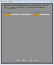
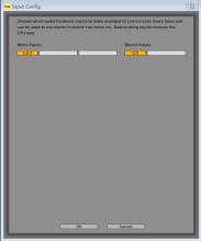
Once the BMG-11S is set as the preferred Audio Device in your DAW, its inputs and outputs Once the BMG-11S is set as the preferred Audio Device in your DAW, its inputs and outputs will appear in your DAW’s Audio I/O preferences. Depending on your DAW, you may will appear in your DAW’s Audio I/O preferences. Depending on your DAW, you may need to enable certain inputs or outputs before use. The two examples below show two need to enable certain inputs or outputs before use. The two examples below show two Inputs and two outputs enabled in the Ableton Lite Audio Preferences.
Inputs and two outputs enabled in the Ableton Lite Audio Preferences.
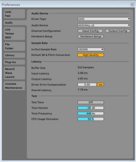
We recommend you download ASIO4ALL Control application, Initially, when In Easy Start
mode, the interface will function at sample rates up to 48khz.Once SIO4ALL Control Is inst
on your computer, you can work at sample rates up to 192khz.
BOMGE BMG-11S is an idea audio in terface for many DAW application
other computer, PC or Mac. Atypical setting of connections is illustrated below.

This setup shows a typical configuration for recording using DAW software on your Mac or PC. You would record vocals through input 1 and guitar through input 2 into your recording applications, while monitoring the playback via headphones.
s0MGEBG-11S inputs are on the front panel. Input 1 uses a standard and both line 3 pins XLR socket, and is designed to work with microphones of most popular types; you will probably have a male XLR connector on the end of your microphone cable.
TABLE CONTENT
If you are using a ” studio” condenser microphone designed to operate on 48
If you are using a ” studio” condenser microphone designed to operate on 48 voltage phantom power, press the 48V button. In some lower spec. condenser voltage phantom power, press the 48V button. In some lower spec. condenser microphones are able to operate from a lower phantom power voltage – typically microphones are able to operate from a lower phantom power voltage – typically 15V. You should check the microphone spec. to see if it is safe to operate it from 48V; 15V. You should check the microphone spec. to see if it is safe to operate it from 48V; if not, obtain a suitable external if not, obtain a suitable external phantom power supply. Most modern microphones of other types, e.g. dynamic or phantom power supply. Most modern microphones of other types, e.g. dynamic or ribbon, will not be damaged by the inadvertent application of phantom power, but ribbon, will not be damaged by the inadvertent application of phantom power, but note that some older microphones maybe; if you have any doubt, please check the note that some older microphones maybe; if you have any doubt, please check the specification of your microphone to ensure it is safe to use. specification of your microphone to ensure it is safe to use.
Input 2 uses a 1/4″(6.35mm)jack socket which is 2-pole when in instrument mode Input 2 uses a 1/4″(6.35mm)jack socket which is 2-pole when in instrument mode and 3-pole when used as a mono line input. It can accept signals from an electric or and 3-pole when used as a mono line input. It can accept signals from an electric or electroacoustic guitar or bass, a keyboard, and most other types of audio electroacoustic guitar or bass, a keyboard, and most other types of audio equipment. Set the INST switch ” ON” ( “INST” illuminates red) if you are connection equipment. Set the INST switch ” ON” ( “INST” illuminates red) if you are connection a musical instrument, e.g., a guitar in the example, using an ordinary 2-pole (TS) a musical instrument, e.g., a guitar in the example, using an ordinary 2-pole (TS) guitar jack. Set the INST switch to OFF if you are connecting a line level source such guitar jack. Set the INST switch to OFF if you are connecting a line level source such as a keyboard, synthesiser or the balanced output of an external audio mixer via 3-as a keyboard, synthesiser or the balanced output of an external audio mixer via 3- pole (TRS) jack. Note the jack socket accepts both TRS and TS types of jack plug. pole (TRS) jack. Note the jack socket accepts both TRS and TS types of jack plug.
USING DIRECT MONITORING
You will frequently hear the term ” latency” used in connection digital audio You will frequently hear the term ” latency” used in connection digital audio systems. In the case of the simple DAW recording application described above, systems. In the case of the simple DAW recording application described above, latency will be the time it takes for your input signals to pass through your computer latency will be the time it takes for your input signals to pass through your computer and audio software. Latency can be a problem for a performer who wishes to record and audio software. Latency can be a problem for a performer who wishes to record while monitoring their while monitoring their input signals.
The unit is fitted with a Direct Monitoring option, which overcome this problem. The unit is fitted with a Direct Monitoring option, which overcome this problem. Setting the front panel DIRECT MONITOR switch to ON will route your input signals Setting the front panel DIRECT MONITOR switch to ON will route your input signals directly to the unit’s headphone and main monitor outputs. This enables you to hear directly to the unit’s headphone and main monitor outputs. This enables you to hear yourself with zero latency. i.e., in “real time”-along with the computer playback. yourself with zero latency. i.e., in “real time”-along with the computer playback. Your inputs will be summed to mono, so both microphone and instrument will Your inputs will be summed to mono, so both microphone and instrument will appear in the center of the stereo image. Note that the input signals to your appear in the center of the stereo image. Note that the input signals to your computer are not affected in any way by the use of Direct Monitor. computer are not affected in any way by the use of Direct Monitor.
When DIRECT MONITORING is set to ON, ensure your recording software is not set When DIRECT MONITORING is set to ON, ensure your recording software is not set to route its input ( What you are currently recording) to its output. If it is, you will to route its input ( What you are currently recording) to its output. If it is, you will hear yourself “twice”, with one signal audibly delayed as an echo. hear yourself “twice”, with one signal audibly delayed as an echo. Monitoring with DIRECT MONITOR set to OFF can be useful when using an FX plug Monitoring with DIRECT MONITOR set to OFF can be useful when using an FX plug in to your DAW to create a stereo effect which contributes to the live performance. in to your DAW to create a stereo effect which contributes to the live performance. In this way, you will be able to hear exactly what is being recorded, complete with In this way, you will be able to hear exactly what is being recorded, complete with the FX. However, some latency may result, the amount depending on the DAW’s the FX. However, some latency may result, the amount depending on the DAW’s buffer size and processing power of the computer. buffer size and processing power of the computer.

SPECIFICATIONS
Performance Specifications

Connecting BMG-11S to Loudspeakers
You can use the 1/4″jack outputs on the rear panel to connect monitor speakers. Active monitors have internal amplifiers with a volume control, and can be Active monitors have internal amplifiers with a volume control, and can be connected directly. Passive loudspeakers require a separate amplifier; the rear panel connected directly. Passive loudspeakers require a separate amplifier; the rear panel outputs should be connected to the amplifier’s inputs.

The line outputs are 3-pole (TRS)1/4″(6.35mm) jack sockets, and are electronically balanced. Typical consumer (Hi-Fi) amplifiers and small powered monitors will have balanced. Typical consumer (Hi-Fi) amplifiers and small powered monitors will have unbalanced inputs, either on phono(RCA) sockets, or via a 3.5 mm 3-pole jack plug unbalanced inputs, either on phono(RCA) sockets, or via a 3.5 mm 3-pole jack plug intended for direct connection to a computer. In either case, use a suitable connecting intended for direct connection to a computer. In either case, use a suitable connecting cable with jack plugs at one end.
Professional power amplifiers will general have balanced inputs; we highly recommend using balanced cables to connect to the outputs of our unit.
NOTE: You run the risk of creating an audio feedback loop if loudspeakers are active at the NOTE: You run the risk of creating an audio feedback loop if loudspeakers are active at the

The front panel includes the input connectors for mic and line/instrument signals,
and the input gain and monitoring controls.
1. Input 1 electronically balanced input via 3-pin XLR socket for microphones.
2. GAIN 1 — adjust the gain for the microphone signal at Input 1. The gain controls have a green colour
LED square to confirm signal input.
3.48V — phantom power switch for microphone input – enables 48 V/ phantom power at the XLR
socket.
4. Input 2 – %” TRS jack socket to connect both instruments (unbalanced TS jack) or mono line
level (balanced) sources.
5. GAIN 2 – adjusts the gain for the linefinstrument signal at Input 2. The gain control has a green
colour LED square as [2].
6. INST/LINE – Instrument/Line level switch for Input 2 — switches gain to suit instrument or line level
signals. ‘INST illuminates green when Instrument mode is selected
7. MONITOR — main monitor output level control – sets the output level at the rear panel outputs
and the front panel headphone output.
8 USB LED — a green LED illuminates when the unit is connected and recognize by your computer.
9. DIRECT MONITOR – selects monitoring of input signals (mixed with the DAW output) to be
directly from inputs (ON) or via the DAW (OFF)
10. %” TRS output jack. If your headphones have a %4” TRS jack plug, connect them directly;
if they have a 3.5 mm TRS “mini jack’, use a TRS %”-t0-3.5 mm jack adaptor. Note that itis
likely headphones fitted with 4-pole TRRS plugs will not operate correctly.

11.K(Kensington security lock)-Secure your unit to a suitable structure
if desired.
12. USB 2.0 port – Type C connector; connect the unit to your computer
with the cable supplied.
13. LINE OUTPUTS: LEFT and RIGHT- 2 x 1/4″ (6.35mm) TRS jack sockets;
Either 1/4″ TRS (balanced connection) or TS ( unbalanced connection)
jack plugs can be used
Documents / Resources
 |
BOMGE BMG-11S Audio Interface Professional Sound Card [pdf] User Guide BMG-11S Audio Interface Professional Sound Card, BMG-11S, Audio Interface Professional Sound Card, Interface Professional Sound Card, Professional Sound Card, Sound Card, Card |


